Announcement

Collapse
No announcement yet.

Bi-toroid Transformer of Thane C. Heins

Collapse
X
 
  • Filter
  • Time
  • Show
Clear All
new posts

  • Dog-One
    replied
    Originally posted by BroMikey View Post
    I am using an AMP clamp.

    This is very strange. I have ordered 2 new meters just alike and will do the same with scope probes.
    Be careful of the Amp Clamps. Many of them cannot run in audio range and is the reason Tektronix sells theirs for $1500 and up.

    If you are buying probes anyway, I'd give some thought to getting a pair of differential probes and just use a small ( < 1 ohm ) shunt for current readings. Diff probes are pricey too, but they make taking measurements so simple because you no longer have to worry about where the ground loops are. You just connect across any two points in the circuit and away you go.

    Leave a comment:


  • BroMikey
    replied
    Power in Power Out

    I have power in the circuit but I am unsure for now, so I retracted my watts in and out figures.

    I am using an AMP clamp. It works but I will use direct lines this time to take more readings. I am running a light load and there is power in the circuit, thats for sure.

    For instance I read 320ma in and then I check each terminal out of four wires coming from the 2 secondaries with readings as high as 800ma.

    This is very strange. I have ordered 2 new meters just alike and will do the same with scope probes. Still I need 2 more cores to make 7 and finish the better windings.

    Right now I am running on mismatched coils. one 180 and the other 170 turns. So I am off balance. I have one round coil and one triangular coil for the secondaries. The primary is round and is not big enough for the cores to all fit.

    Got to finish winding proper coils. Still i wanted to see what this BITT is like.

    Mike

    Leave a comment:


  • BroMikey
    replied
    Thanks Wayne

    I agree Dave's video is really professional and thanks for your kind words. Glad you are there building as well.

    Mike


    Originally posted by wayne.ct View Post
    Hi Dave,

    I watched your video and want to compliment you on your clear and thoughtful narrative. I have watched a number of videos on the BiTT/SFT and yours is one of the best. Thanks and I recommend it.


    I like Mike's suggestion that we need a small (portable) circuit to provide the input signal and provide an automated frequency adjustment, etc. It would have many advantages. I commend you, Mike, for staying focused. I only hope my build is as successful as what I see you doing here.

    Leave a comment:


  • BroMikey
    replied
    Looper Running Down

    Hi Dave

    Great to see someone who HAS done their homework. The type of person who does their homework so to speak is one who collects data when they are half asleep because the experiment is part of them and always going on inside of them in that chamber of imagery.
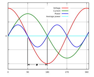
    We all have heard that this was the way Tesla did some of his experimenting though his was advanced we all do the same thing.

    Glad to meet someone like you, not everyone is gifted in all the same ways.

    You know I can not find that link with the circuit running for a few minutes as it slowly drops down but remembering back we all watched Lasersaber do the same thing with so many of his joule ringer.

    The thing about getting extra energy is you need to have some to start with . We all have heard this as well. A special set of windings at a certain voltage, frequency, flux path arrangement and then the moment we all have waited for arrives.

    We tune and tune to get the max.

    I think it important that we maintain that tuning anyway possible and of course this is why we have the circuits. I know I sound redundant.

    These cheater examples (is what I call them) where one wire hooks from the front to the back is a great way to demo without meters. It only lasts for a few minutes and then you could throw out another pulse and then your circuit is back up to full again til she winds on down.

    Trust me Clean has scopes on top of scopes with phase angles on display.The reason he doesn't focus on that exclusively is because tuning by a scope can keep you from finding the secrets of any circuit.

    Plus no matter how hard an experimenter tries to explain and prove free energy with meters there is always another comment that is made that the meter must be bad, do you have an extra one? and so on. You must have made a mistake? You need to go back to school?

    You know all of the bull roar, low life comments, that take the fun out of sharing. Some arm chair commander ready to smear everyone because he is the ultimate authority. You know the type. These guys blab, that's all they do.

    Clean has determined that he will not be side tracked by anyone or anything. Also he will not be answerable to anyone. I completely understand why people react this way and to them all of the bickering over the meters failing is not worth it.

    This is what I think about why he doesn't try to prove this stuff. He has but like you say he doesn't focus strictly on empirical evidence.

    Looping shows a great effect that no other circuit can show. With that evidence allow it can be more convincing to the average person who searches for extra energy design than meter reading.

    The Engineer looks at it both ways.

    If you have never seen looping experiments check out the joule ringer videos they are all the same with some of the circuits running down slower because the single LED does not draw much. Plus the sneaky little SUPER CAPACITOR
    that appear to look like a normal capacitor ARE NOT NORMAL.

    However this last looper produced using the Joule Ringer coils have an additional windings that collects more of what would normally be wasted.

    They all run down, they are not completely self powering and they do not operate at peak efficiency at all points between full and dead.

    All good questions. I have pondered these same ones for sometime now.

    Super set up Dave stick to your guns (Empirical evidence) and don't change anything. Just tune it, refine it by adding more compact circuits to make it a practical device.

    This makes you one of the few who actually has extra energy in abundance.

    Mike


    Originally posted by Web000x View Post
    Mike,

    I would love to see Mr. Clean unhook his circuit from his battery and have the thing continue to run.


    Please post a link to that.


    As far as I can tell, Mr. Clean has showed nothing that I would call a 'solid' measurement of power. All of his observations are qualitative, with very little attention to phase angles.
    Dave
    Last edited by BroMikey; 10-13-2014, 04:59 AM.

    Leave a comment:


  • wayne.ct
    replied
    Good explanation, Dave

    Hi Dave,

    I watched your video and want to compliment you on your clear and thoughtful narrative. I have watched a number of videos on the BiTT/SFT and yours is one of the best. Thanks and I recommend it.


    I like Mike's suggestion that we need a small (portable) circuit to provide the input signal and provide an automated frequency adjustment, etc. It would have many advantages. I commend you, Mike, for staying focused. I only hope my build is as successful as what I see you doing here.

    Leave a comment:


  • BroMikey
    replied
    ReGenX

    I can understand how the reGenX can into being. First Thane discovered the reflected wave recovery method in the BITT that extracts energy for the environment.

    Then just like Bill has increased frequency through the use of complex circuitry, thane decided that the Bi-Toroid principle could be applied to an electric motor At the same time generate the elevated voltages and frequencies needed to increase efficiency.

    The motor simplifies the circuitry needed to run it. Simple means less waste. A motor that accelerates under increased load meaning that the design runs on idle at average efficiency and as power is needed and RPM increases the machines optimum COP doubles and triples as it climbs.

    What an awesome idea. I never read anything about that creation anywhere. It just came to me.

    I have been to busy building these simple BITT's.

    Mike

    Leave a comment:


  • BroMikey
    replied
    Right on the Math

    That math equation is inescapable. The power companies live eat and sleep KVAR's. That is all they understand, anything else is not a consideration and all of their calculations can never be changed.

    They know their job and will always do it the same way as required or they lose their jobs. I talk to a few who i ask questions and they don't give an inch. They want soft start and to see the angles AND THEY TELL YOU what cap to ad in if you pay them enough money to come out and inspect your operation.

    They don't budge. You are right Web000x, it is what it is and the power company rules have been like this for 100years.

    Mike


    Originally posted by Web000x View Post
    I can feel the 5.4 watts of power being dissipated in my load resistor. In that setup, you can do the math from the video of how much power is across the load. Look at the 90 degree phase shift on the scope where even a slight fraction wouldn't do much damage to some amazing COP calculations. How do you explain it?

    Dissipating 5.4 Watts across 54 Ohms of resistance, synchronicity of 1:10...

    Voltage at Primary: 24.1 Volts

    Current into Primary: 1 Amp

    Cosine = 91.8 degrees [(4.08uS/8uS)x180]

    INPUT POWER = -.756 Watts


    The former were my measurements. Let's get hypothetical... The cosine angle that you, Farmhand, would need to account for my measurements of 5.4 watts would be 77 degrees. Obviously that angle that I show in my scope shot is far closer to 90 degrees than 77 degrees. By the way 77 degrees would be a transfer rate of aproximately 100% with no core losses. Do the math.

    Dave

    Leave a comment:


  • BroMikey
    replied
    Flux path Experiments


    @Dog-One Bills smart pack circuitry mainly centers around keeping that expensive battery alive for many years. Bill knows about all of the battery technology such as changes to duty and spiking so his embedded chip can be written to both monitor and charge.

    Proper charging is VERY SIGNIFICANT. And his smart pack will do better charging than any other system besides John B.

    What a chip might do for the BiTT is change the amptitude so the amount of energy going to the battery drops off as SMART charge cycle progresses. So the chip can be programed for all of these important timing moves.

    If you are not going to charge batteries running a BiTT wide open is a far easier operation. As far as looping goes I have come to realize that the simple forms of just sending some power back through a resistor will suffer an ever diminishing frequency change. This will throw off the efficiency of the BITT by straying from the best waveform.

    Set up a circuit that works and later send plenty back to the battery in pulse form with lots to spare for running your loads.

    Mike
    Last edited by BroMikey; 10-13-2014, 12:06 AM.

    Leave a comment:


  • Web000x
    replied
    Originally posted by Farmhand View Post
    Another thing to remember about Thanes BiTT is the tiny load powers he was
    demonstrating
    , the lower the power the more magnified any measurement
    errors will be. A fraction of a degree off 90 degree phase shift would likely
    account for his results
    I can feel the 5.4 watts of power being dissipated in my load resistor. In that setup, you can do the math from the video of how much power is across the load. Look at the 90 degree phase shift on the scope where even a slight fraction wouldn't do much damage to some amazing COP calculations. How do you explain it?

    Dissipating 5.4 Watts across 54 Ohms of resistance, synchronicity of 1:10...

    Voltage at Primary: 24.1 Volts

    Current into Primary: 1 Amp

    Cosine = 91.8 degrees [(4.08uS/8uS)x180]

    INPUT POWER = -.756 Watts


    The former were my measurements. Let's get hypothetical... The cosine angle that you, Farmhand, would need to account for my measurements of 5.4 watts would be 77 degrees. Obviously that angle that I show in my scope shot is far closer to 90 degrees than 77 degrees. By the way 77 degrees would be a transfer rate of aproximately 100% with no core losses. Do the math.

    Dave
    Last edited by Web000x; 10-12-2014, 07:18 AM.

    Leave a comment:


  • Web000x
    replied
    Originally posted by Farmhand View Post
    BroMikey that setup can show any phase angle you like, and it does show
    phase angles of over 90 degrees and the same effects as Bill Alec's
    transformers, I can dig up some 90 degree load shots which Thane would call
    OU, I can show phase angles of 90 and Zero degrees on either side of a
    Transformer powered by the setup. All that is possible because it's a "Tuned"
    circuit and I can adjust the capacitance in the tanks very finely.
    So you're telling me that you're going to explain away conventional phase angles with some newly contrived theory based off of your personal hunch? Power companies are very concerned with this particular subject of phase angles. Do you think they just pass it off as some 'phenomena'? What do you think they might see if they saw that on the transmission lines?
    Oh, the load just accidentally sent 100's of KW worth of power spikes back to the generator with no apparent source, no cause for concern?

    Dave
    Last edited by Web000x; 10-12-2014, 05:52 AM.

    Leave a comment:


  • BroMikey
    replied
    My First Bi-Toroid experiments

    One other thing I didn't mention was the fact that I randomly hooked my secondaries in parallel with each other. One way gives me twice as much voltage as the opposite way that is half the voltage.

    Anyone doing this experiment needs to try both ways so they can get the effects right. The connection that displays the effects is a bifilar one? I don't know what it's called.

    I ran out of time. Be doing more in series next.

    So this may explain why so many get poor results

    Keep trying, winner takes all, losers take the fall.


    Mikey
    Last edited by BroMikey; 10-12-2014, 05:27 AM.

    Leave a comment:


  • Dog-One
    replied
    Maybe an elegant solution just around the corner...

    Originally posted by Web000x View Post
    You certainly are correct Dave. There is extra juice being extracted and it has to go somewhere--either out the secondaries or the primary.

    I need to do some thinking about the shorted condition. If we had the right kind of driver circuit, essentially the SFT gain could be pumped over and over until like you said, it simply blows up. The beauty here though is that we have an extraordinarily high (Q Factor) gain inductor. There must be a simple straightforward way to take advantage of that condition.

    Is it possible to just construct a tank circuit and pulse it initially to start it, then just let it ramp up on its own to some threshold where we bleed off the excess power to avoid self destruction? Could it be that simple? This would beat Bill's over complicated SmartPAK for certain. How about a simple bridge rectifier, filter cap and adjustable voltage regulator connected to a load? Would this act as a bleeder circuit?
    Last edited by Dog-One; 10-12-2014, 04:45 AM. Reason: More content

    Leave a comment:


  • BroMikey
    replied
    conventional training

    Here is a basic understanding of conventional power factor training. No need for confusion.


    https://www.youtube.com/watch?v=81n7HrLn3Ng


    https://www.youtube.com/watch?v=vO6iEPLdrdQ


    AuroraTek at Prepper Fest AZ Expo 2014 on Vimeo


    Mikey
    Last edited by BroMikey; 10-12-2014, 01:48 AM.

    Leave a comment:


  • BroMikey
    replied
    BiTT Power Factor

    Here is part one


    https://www.youtube.com/watch?v=45M4mCKrxTM

    Leave a comment:


  • BroMikey
    replied
    Finding the truth

    Anyone can produce any wave shape they want but to look for the truth in this setup you will need a transformer built as instructed.

    Without a Bi-Toroid Transformer or some kind of a similar split phase transformer then you can never get the proper results. It looks like you are looking for results that back up the old EM laws.

    Naturally know one is surprised as this has always been your way. First you should test a Bitt before making any judgements.

    I think the problem you are having is the part about energy being returned to the supply as one form of extra energy. You have to start at the beginning.

    At the end we will have a closed loop and it will not be until then that each man will know for sure if his system in tuned.

    Here is your parts list.

    1 Get some metglas cores of the proper proportions

    2 Produce a 3:1 ratio of magnet wire windings

    3 1 deep cycle battery.

    4 sinewave inverter variable frequency oscillator for 12vdc supply

    Other feed back systems to recharge the battery and you have completed your design.

    Anything short of that has nothing to do with this thread and belongs in the file marked "SOMETHING ELSE"

    Show me and the group your Bitt under load.


    Mikey


    Originally posted by Farmhand View Post
    BroMikey that setup can show any phase angle you like....................................

    I'm looking for the truth of the matter, I'm not trying to verify any particular
    side of the argument, I just want the truth and I will find it, if other do not
    accept what I find out then that is their right.

    Bill Alec uses frequency in the Khz, truth is they use the frequency that suits
    the coils or they make the coils to suit the frequency, no real difference.

    ..
    Last edited by BroMikey; 10-12-2014, 01:04 AM.

    Leave a comment:

Working...
X