
BroMikey that setup can show any phase angle you like, and it does show
phase angles of over 90 degrees and the same effects as Bill Alec's
transformers, I can dig up some 90 degree load shots which Thane would call
OU, I can show phase angles of 90 and Zero degrees on either side of a
Transformer powered by the setup. All that is possible because it's a "Tuned"
circuit and I can adjust the capacitance in the tanks very finely.
With this setup and a couple of others I can show all the effects produced
by Than Heins, and I think I can explain the Bitt effect but I need to do some
more experiments.
I have shown the acceleration under load effect ( regenerative acceleration)
he called it and I can show a significant reduction in input power when
powering a load from a regular transformer as in his Transformer based setups.
I have no doubt I can explain the effect seen in the Bitt, but I will need to
build a line frequency one to show it, problem is that I will be showing why it
isn't over unity like he claims while showing similar results effects.
One thing to remember is that it is not possible to maintain a 90 degree
"exactly" phase shift between voltage and current on the input because if
that was the case no energy could be transferred to the load, in reality
the phase angle between voltage and current is always changing slightly,
if the phase between voltage and current on the input was maintained at
exactly 90 degrees the real input would drop to zero.
Another thing to remember about Thanes BiTT is the tiny load powers he was
demonstrating, the lower the power the more magnified any measurement
errors will be. A fraction of a degree off 90 degree phase shift would likely
account for his results
If Thanes acceleration under load effects are not what he claims they are
then why is it not possible he is wrong about the BiTT as well ?
The composite picture from my last post was actually for the different stages
of lighting a fluro.
I'm looking for the truth of the matter, I'm not trying to verify any particular
side of the argument, I just want the truth and I will find it, if other do not
accept what I find out then that is their right.
Bill Alec uses frequency in the Khz, truth is they use the frequency that suits
the coils or they make the coils to suit the frequency, no real difference.
..
-
Dave's Video
Hey Dave
You are indeed an electronics master. The video is worth thousands of words.
All I can think is where can I get a scope that is more contemporary so i can see waveforms this nice. You have shown a very important effect of negative power factor and real heat dissipation.
This is yet another super validations. This leaves very little to question, doesn't it
Keep exploring the new possibilities of practical use.
This is only the first hurdle. That split flux trans is way bigger than I had originally thought.
Thanks for sharing all your work up to this point math included,
Mike
Originally posted by Web000x View PostLast edited by BroMikey; 10-11-2014, 08:57 PM.Leave a comment:
-
Lesson in Grounding
Hey Farmhand
While the setup you have from the past does not exhibit a Bi-Toroid wave form we (or I) have much to learn about operating high frequency supplies so your comments really do help solve certain technical problems.
I for one am willing to admit that there is always something to learn from others such as yourself. Not that I don't know the basics about your entry, because I do. Yet I think experimenters need to be kind to one another and see what each man is able to offer.
Thank you for your kind regards to show what you DO know about the direction that we are going. There is much I do not know about the intricate details of various types of circuitry and I say this unashamedly. What am I going to do? Tell everyone I know it all? This makes me a fool. Not this kid.
I have forgotten more than I remember sometimes so please refresh my memory so I will focus once again on the subject matter.
The thing I see with shielding and grounding at high frequencies is separate battery sourcing especially in the presences of high voltages. I was watching Aaron do this in one of his ED GRAY TUBE video's, he is not the only one who i have watched do that, just the most recent in the video's I watched.
We need to first focus of getting the effect up and running at any freq and any voltage. It is inevitable that we are going to need some serious circuitry for running these simple windings to their resonant harmonic or wherever we end up.
I think you are right FarmHand to keep the voltage down when taking measurement yet the temptation to see the waveform at higher levels will always exist.
I will admit that I have been out of touch with what we have covered in most of this discussion so every little bit I can pick up again to sort out in the pile of facts is always welcome.
Working together for a common goal using each mans abilities is what a corporate manager does. He is the boss and HE tells everyone to jump and how high they can jump and when they all get their paycheck everyone is happy.
On the other hand many bosses are nothing but discussing heady jerks who make it difficult to work for a measly buck and get only nominal production from the collective work force.
The corporate world teaches us about competition so THAT part can be a good thing however the arrogance associated with destroying a work mates character in full view of the public eye in order to make themselves a position higher has always ended in a mess.
What we need is grace, this very important word should be mixed with all of out interactions with one another. I see each one of us doing just that. In the best settings I have worked in no one person is an island unto themselves.
They share what they know and playfully use a joking slapstick wording designed to get the other man thinking and back into the competition.
So with that said maybe each one could offer what he knows and when the other man falls far short and we see it, don't make a big mess.
This is the way for experimenters to work together without doing it for money.
For instance I need a simple circuit to generate ac sine waves powered by a 12vdc battery. This part is not so bad but I also need an oscillator that can run 100 volts at 10,000hz all the size of a lunch box.
Or even make it the size that fits into a flash light.
I know it sounds far fetched but I want a small battery running a sinewave or close as possible, an AC converter using the standard coil method to form what is known as a VFO. I don't want a huge rack mount signal producing generator hooked to some bulky audio amplifier that puts out a low voltage for the rest of my experimenter days.
So this is a big task for me. Not to big just sizable.
Yes this is the Bi-Toroid thread and in this field of invention it is going to take everything I have learned in radio work as well as switch mode to pull this job off, so I need every bit of help I can get.
I won't start a job unless I am sure it can be finished. I have deemed this device worth while a few years back so what you see me post has been something that has been brewing for quite some time now.
We have bit off a big chunk gentlemen and it will take all of us and then some. Our advantage is that Thane, Bill, Clean and many many more can be seen proving some aspect of the invention.
If anyone can help me get or find circuits that are small to build a VFO at 100volts I am all ears.
Beyond that the high frequencies and high voltages do not have many amps to accompany, may be lethal to the inexperienced Joe Experimenter so I advise caution.
I see guys taking a modified sinewave INVERTER to make the frequency adjustable but this form of change does not give a broad enough range for testing purposes. In time a set frequency will become known for a specific Bi-Toroid coil set and at that point it will be interesting to see if this approach can be utilized.
Kind Regards
Mike
Originally posted by Farmhand View PostLast edited by BroMikey; 10-11-2014, 08:11 PM.Leave a comment:
-
Here is a less than awesome quality video showing my setup. I tried using the HD function but it wouldn't load so I had to settle for standard quality.
https://www.youtube.com/watch?v=7mCx...L6cdsupqwo9-Hg
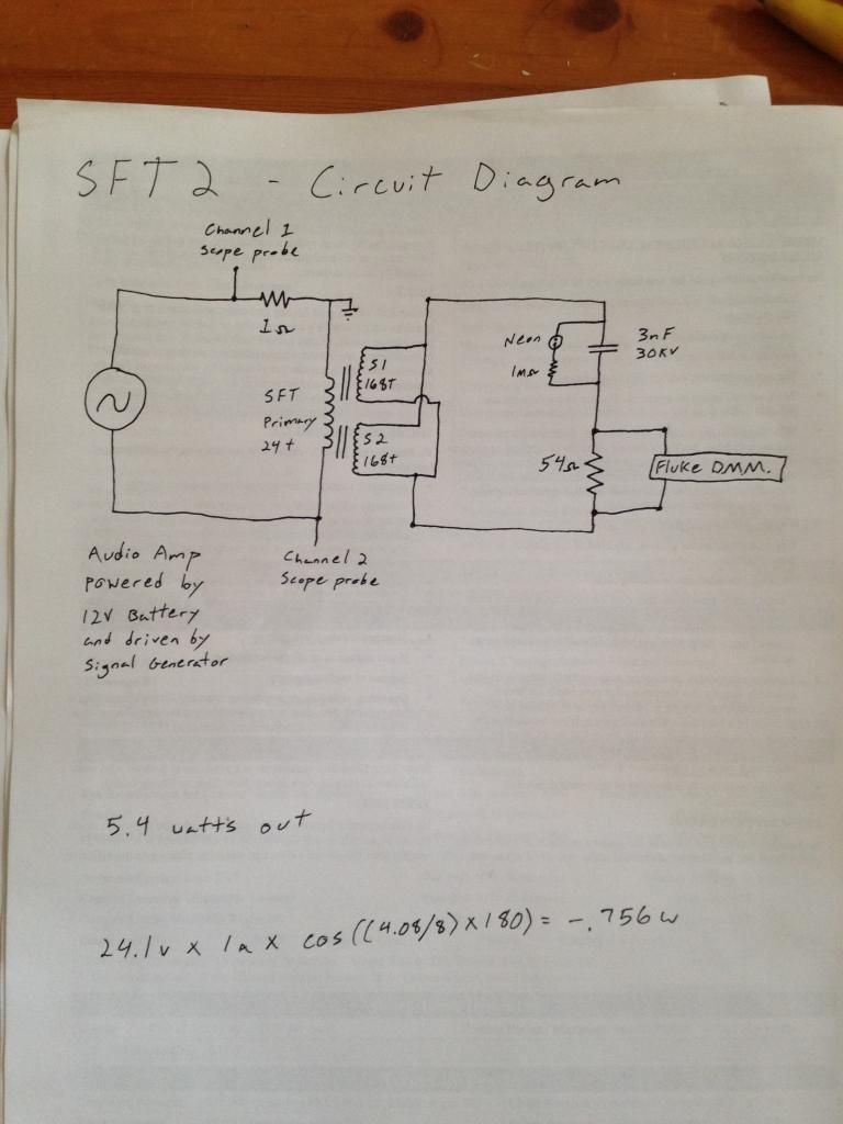
Here is my schematic:
Dave
P.S. I made a mistake in a previous post saying that my turn ratio was 1: phi^3. I was mistaken. It is 1: phi^4, or 24:162. The schematic also wrong. It says 168 turns on the secondaries, but it should say 162 turns.Last edited by Web000x; 10-11-2014, 08:05 PM.Leave a comment:
-
This analysis is crucial Dave. I need to let it sink in a bit more. On the surface it seems there is something about having a split flux path that is giving us gains here that would otherwise not be observable with a conventional transformer. I probably need to draw up the circuit and apply all the formulas--maybe we can peer into the math enough to determine where the sweet spots are.Originally posted by Web000x View Post
BTW, I really appreciate you using the terms dielectricity and magnetism. This helps a lot in understanding, especially if we view this device as a transmission line; one that splits and creates two new transmission lines. We may even have to tap Eric on the shoulder for a few moments and see if he can enlighten us just enough so we can take this the rest of the way.Leave a comment:
-
The grounding is a good point to bring up, from what info I've got from some
engineering types on the other forum I need arrange the setup and the scope
so that the influence of a ground loop is minimized. Also for my high
frequency setup 420 kHz I need to make sure there is minimal influence of
the field of induction on the measurements, which might mean keeping the
voltages down.
With that setup the tuned tanks can see voltages of over 1.6 Kv p to p and
some amps of current. With only 12.3 or so volts and under 1 amp, my
power supply is limited to 1 amp and does not take a reverse current, but my
primary switching circuit is DC and has a reflecting capacitor across the mosfet
so it can run with no secondary and gets about a 40 volts DC lump which
excites the secondary tanks.
But I can load it down and tune the tanks to either side of resonance and even
down to the lower harmonic. Would work better with an AC switched primary
but as you can see I get perfect sine waves on the secondary tanks and I
can also power transformers from the tanks in a few ways, which is where
I will do my tests, the main arrangement is merely a generator of HF AC, which
will be a pseudo "grid" for me, reactive power cannot re-bury coal and undo
the work it took to generate the power in the first place. So my supply not
taking power back there is not a problem and it doesn't cause any problems
for me with my own switching circuit which turns the primary transients into
a higher primary voltage.
Attached is a shot of my mosfet drain (blue) and final output (yellow) some shots of Tank voltages
the 1.6 Kv and a shot of a lower voltage and current (blue) sensed across a 0.1 Ohm
resistor, HF so phase is off.
The composite picture kinda goes with the videos but is only the Tank shots,
..Last edited by Farmhand; 10-11-2014, 08:13 AM.Leave a comment:
-
No Surprise
Originally posted by Web000x View Post
It is no surprise to me that all of our standard circuits are only designed to BURN power, not USE power effectively. Sending power back to a circuit pushing OUT power will cause stress.
The point is very revealing that you have in fact overloaded and burned out your amp using a 1/4 watt of it's power output capability.
Great results. A tube amp can take a lot more beating than those tin can digital boxes built these days from WAL-MART.
Can you imagine what these circuits will produce pushing 5000hz at 200volts?
This will require some doing. Right now we are only able to output a few volts from our puny little audio amplifiers.
Great experiment showing things that we wouldn't normally expect to see like smoking your circuits on a 1/4 watt.
MikeLeave a comment:
-
I was going to make a video for you all to see but it seems my audio amplifier has seen too much reactive power sent back to it. It doesn't seem to work right anymore.. I don't have the means to recover tonight. Maybe I'll scrounge up some parts for my tube amp.Leave a comment:
-
I didn't want to claim anything. I have been wrong before, but I keep throwing test after test at this circuit and I can't find any potential flaws. The only thing left to do is find some resonance or build a generator to find out as my audio amplifier will show me nothing..Originally posted by BroMikey View PostLeave a comment:
-
When you look at impedance matching in terms of how much power actually makes it to the secondary load, then this starts to make a little more sense. Take a look at this page: Maximum Power Transfer Theorem : Dc Network Analysis - Electronics Textbook. Notice how a lower impedance load does make the system draw more power, but the load is still not seeing its maximum possible power dissipation. This means there is a disposition of this circuit to contain more stored magnetism than dielectricity, hence 'not impedance matched'. This is where my circuit likes to operate. We have to stay 90 degrees out of convention here so it makes sense that a shorted secondary (MAXIMUM STORED MAGNETIZATION) would produce better results. Something about the stored magnetism is returning more. Parameter variation as proposed by Dollard?Originally posted by Dog-One View Post
DaveLeave a comment:
-
Leave a comment:
-
FarmHand Man
Hey FarmHand
I sure will check it out. Hope you get better. I know it will be just like that. When you are well things are going to change. These experiments like you have posted are changing the face of excess energy producing circuitry.
Here is a well known for your review.
https://www.youtube.com/watch?v=6WPpRjSSnAw
Don't give up, free energy is a myth but with a little input we can get more back and in time someone will have a free running garden light like John Bedini has.
Mikey
Originally posted by Farmhand View PostLeave a comment:
 you couldn't get it remember?


Leave a comment: