Announcement

Collapse
No announcement yet.

Bi-toroid Transformer of Thane C. Heins

Collapse
X
 
  • Filter
  • Time
  • Show
Clear All
new posts

  • vidbid
    replied
    Us20140253271

    Originally posted by vidbid View Post


    Posted drawing by Vidbid
    Heah, look. Doesn't the drawing in Thane's patent look like my drawing?

    The present invention relates to electrical transformers and, in particular, to improvements to efficiency in energy conversion in electrical transformers. The improved transformer has a bi-toroidal circuit topology in which the magnetic flux passing through the primary and secondary coils are different. The turns ratio displays an “effective magnification” like an impedance transformed by a feedback loop. The result is a transformer which displays virtually no primary input current increase from no-load to on-load and an on-load power factor of zero for a purely resistive load.


    Attached Files
    Last edited by vidbid; 12-01-2015, 04:52 AM. Reason: corrected link

    Leave a comment:


  • BroMikey
    replied
    You Are Awesome

    As far as I am concern, you are one of the most conscientious well spoken individuals I have encountered. You will do great things. The reason I brought up EE attitudes is that it can be an obstacle. In EE there are many branches of DEEEEEEEEP understanding that to me is all about sales of more school time.

    Just look at the junk with the atom smasher that never quite reaches Fusion after billions and billions. The big money does not want us to learn the simple truth so they plant stumbling blocks in the minds of their school boy cronies.

    As far as I am concerned the high brow college professor is endoctrinated in arrogance. They only know what they are told to know. Blind Dogs.

    Thanks for hearing me rant wayne, you make a great sounding board

    mike


    Originally posted by wayne.ct View Post
    Yes, I understand.

    Thanks for the quick reply.

    I don't mean to set myself up as an expert. I am only trying to offer up what I hope will help. I would like to replicate what others are doing, but that is not always possible. I find that there are always differences between what I build and what I see. If my results were to happen to be better, I would gladly try and share because that would be constructive. Negative results don't prove anything. There are too many things that don't work and plenty of people out there and on this forum that take pleasure in being negative.

    I am learning, too. And, I have plenty still to learn.

    Leave a comment:


  • wayne.ct
    replied
    Thanks and so on

    Yes, I understand.

    Thanks for the quick reply.

    I don't mean to set myself up as an expert. I am only trying to offer up what I hope will help. I would like to replicate what others are doing, but that is not always possible. I find that there are always differences between what I build and what I see. If my results were to happen to be better, I would gladly try and share because that would be constructive. Negative results don't prove anything. There are too many things that don't work and plenty of people out there and on this forum that take pleasure in being negative.

    I am learning, too. And, I have plenty still to learn.

    Leave a comment:


  • BroMikey
    replied
    Late Night testing

    I am not sure what the precise phase angle is other than it shifts over a tiny bit from 90 degrees. The choppy wave? I get a choppy wave as soon as I use tuning caps but it looks like a big shift in phase angle so I am guessing a 55-60 degree COS multiplication. But again it was late and I got confused on every reading. I had too many results.

    I will continue and do videos. This is a long drawn out process if done right. Mr Clean is the only serious experimenter out here and he is you example of how to find answers. Years of research is the right way.

    What I am starting to see is that no one really knows the answer to all of the questions that arise. Everyone has a big title in the engineering dept but this stuff does not apply to the old box.

    Mike


    Originally posted by wayne.ct View Post
    These two diagrams were interesting and deciding what is the load is a good question. My observation is the two adjustments of frequency and duty factor allow for some tuning. It bears some consideration.

    Regarding your recent results, Mike, do the .21 watts in/ .41 watts out figures go with the clear scope shot or the "choppy" scope shot?
    Last edited by BroMikey; 11-08-2014, 11:33 PM.

    Leave a comment:


  • wayne.ct
    replied
    Laser Hacker diagrams

    These two diagrams were interesting and deciding what is the load is a good question. My observation is the two adjustments of frequency and duty factor allow for some tuning. It bears some consideration.

    Regarding your recent results, Mike, do the .21 watts in/ .41 watts out figures go with the clear scope shot or the "choppy" scope shot?

    Originally posted by BroMikey View Post


    Leave a comment:


  • BroMikey
    replied
    Nice info

    Good progress fore sure. Can't wait to see what this might work into after several months of rigorous tests. Seems like there must be a secret not shown that only hard work will uncover. 101 percent efficient is kool but not practical.

    I started another thread that is more for the beginning stages of this work by using Thanes page to simulate this process of finding the keyhole to unlock a big door.

    We all know it can be done. Especially with battery chargers being sold without an AC cord to plug into the wall

    Mike


    Originally posted by Dog-One View Post
    I used a $100 roll of Litz wire already; it works slightly better on these Amorphous cores and quite a bit better on the toroid cores like Dave's at high frequencies. Trouble is, my amp can't go high enough to really see something. So "better" means slightly less losses in the wire, but nothing special. But it's a bearcat to wind carefully without tearing it all up. There has to be a better way.

    There probably is something to the windings, but I have a hunch it's proprietary--my guess an annealed MuMetal. This would explain why Bill's wire is much higher resistance than you can get with copper.

    Anyway, until I hit upon something, you are more than welcome to keep going on this thread. I'll keep my thoughts to myself I reckon.

    Leave a comment:


  • Dog-One
    replied
    Originally posted by BroMikey
    Dude don't you think that there is quite a difference in Thanes 1000feet of professionally wound transformer and your few feet of house wire?

    You have great cores. Bad wire and I guess you have not got you litz wire yet and will be going another direction.

    I can start a new thread. I can stand it here. You said it right in the beginning that we could split up. I don't see us working together.

    Dave is out and you don't think it works so there you have it.

    Discussing. BYE I am pulling out boys.

    I used a $100 roll of Litz wire already; it works slightly better on these Amorphous cores and quite a bit better on the toroid cores like Dave's at high frequencies. Trouble is, my amp can't go high enough to really see something. So "better" means slightly less losses in the wire, but nothing special. But it's a bearcat to wind carefully without tearing it all up. There has to be a better way.

    There probably is something to the windings, but I have a hunch it's proprietary--my guess an annealed MuMetal. This would explain why Bill's wire is much higher resistance than you can get with copper.

    Anyway, until I hit upon something, you are more than welcome to keep going on this thread. I'll keep my thoughts to myself I reckon.

    Leave a comment:


  • Dog-One
    replied
    Originally posted by BroMikey
    You Dog You, holdin out on me weren't ya?
    No, mostly just trying to fully understand what we are dealing with here before I go post a bunch of stuff I have to eat.

    To me the SFT can be best described as a wattage regulator. This is when run with a true sine wave AC input. With just the right load, you can get it to 100% PF. Anything higher or lower than this resistance, the PF drops. So far I have seen no sign of any negative PFs. So running it in this manner is pretty much unproductive. Why would anyone want a transformer that only transfers full power with an exact impedance match. And when I say full power, I mean input equals output.

    So next I need to setup for pulsed DC. I think to start I'm going to dead short the secondaries and try a tank circuit on the primary with pulsing to match the natural resonance and see what gives. I highly doubt to see any sort of runaway condition, but that sure would be nice. If that reveals nothing, next I'll try replacing the shorted secondaries with caps and see where that leads.

    Anyway, I can concur with Dave's findings at this point. There doesn't appear to be anything special here so far. Still a lot of testing yet to do though.

    Leave a comment:


  • Dog-One
    replied
    Time for DC Pulse Testing

    Originally posted by BroMikey
    The signal must be produced using a DC source. (A battery in this case)
    Ah Hah!

    Yes, that's the next thing I need to try, pulsed DC.

    I have run the gamut using an audio amp with an AC sine wave and have a pretty good feel for how the SFT responds. It truly is an odd device. With no load it will free-wheel like any inductor or unloaded transformer. Also at a full dead short it will do the same thing. But when you have a normal load, like a filament lamp, it starts to draw power much like a conventional transformer.

    It also appears the windings aren't nearly as critical as I first imagined. My current setup is using large gauge insulated wire, with nearly identical results.

    Here's a pic running a lamp at about an 80% power factor.
    Attached Files

    Leave a comment:


  • BroMikey
    replied
    Wave broken

    Okay I checked it again today. The upper wave is current, the lower wave is voltage. The thing is when I connect caps to the primary for tuning I get a broken up wave. The caps were changed out for the same caps just different ones but still the same broken wave for current.

    This is a job for superscope man. This wave reminded me of the SERPS.

    Its kind of all broken up. Pretty Kool one of a kind wave.

    If I just run the BiTT with no caps the sine wave is pure. I have been confusing the second wave which is current with the output in previous post,Sorry!!

    I am a beginner and a pretty bad reporter

    The main thing is I don't know what this means for the primary current.

    It is a chopped up wave with some ups and downs, spikes.

    During this test the loaded to NO LOAD change in phase is 5 degrees but to be sure I said 10 degrees.

    With the scope shot and tuning like this here are the latest figures.

    Input 6.85v X .182a = 1.25watts X COS 80 degrees = .21 watts real power

    output 4.25v X .097a = .41 watts real power

    COP over 100 percent mission accomplished.

    Mike


    Originally posted by BroMikey View Post
    This first wave I got tonight is with no load and no tuning caps.


    This next wave is fuzzy because I can't get the scope to settle down but this is a loaded wave with 4 large tuning caps. 3 on the primary and 1 on the two secondaries. Pretty crappy AAA? DOG?

    Of course the input wave is on the bottom.

    Strange wave on the output.


    Mike

    Leave a comment:


  • Dog-One
    replied
    Interesting circuit Mike, but where's the output?

    Does the transformer some how push back to the 12 volt power bus?

    Leave a comment:


  • BroMikey
    replied
    Diagrams


    Originally posted by mr.clean View Post
    Hi everyone thankyou, but i just hope to live up to the expectations now

    one thing i know for sure, anytime i have ever taken the positive off the battery, the system totally stops, and here with this unique setup, it kept going, so im optimistic.

    it is very hard to replicate the effect, but im trying to systematize the process, there is a VERY fine setting on signal gen, and to tell you the truth im having difficulty replicating it, but bottom line is its all there, just have to understand it.

    i still am trying to figure out why it would rise up and down, then always back up tho if i manipulated a few small, seemingly insignificant things, but made it come back for whatever the reason.

    even the last radiant circuit i was using with the 2 transistors couldnt keep itself going like this,

    anyway in trying to figure out any possibilities i thought maybe its the 9 volt in the signal gen driving the base of transistor..... but its not, the signal gen is isolated from the "supply" current, so im still stumped on what was making the meter rise as the bulb was lit


    Mike Enjoy these posts

    Leave a comment:


  • BroMikey
    replied
    Looping

    Hey Dave

    Here is the video you requested of Cleans Looping experiments.

    If you did your homework on Clean you would have already watched 39a,39b,39c,39d,39e I did post them here on this page.

    He starts with fast saturating dc pulses and changes to the zero crossing circuit. Enjoy the ride. It is very real. Laser Saber has done this with smaller circuits.
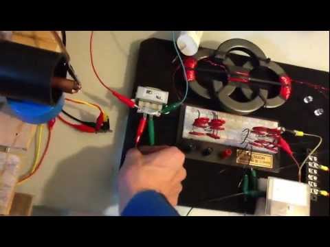
    https://www.youtube.com/watch?v=mzE-p0GJb_Q


    Last edited by BroMikey; 11-07-2014, 02:16 AM.

    Leave a comment:


  • Dog-One
    replied
    Originally posted by BroMikey View Post
    This next wave is fuzzy because I can't get the scope to settle down but this is a loaded wave with 4 large tuning caps. 3 on the primary and 1 on the two secondaries. Pretty crappy AAA? DOG?
    Not sure what I'm looking at there Mike.

    As Dave mentioned, your input signal seems a little distorted. Are you still using a Variac at 60Hz for your source signal?

    Leave a comment:


  • BroMikey
    replied
    Phase Shift

    This first wave I got tonight is with no load and no tuning caps.


    This next wave is fuzzy because I can't get the scope to settle down but this is a loaded wave with 4 large tuning caps. 3 on the primary and 1 on the two secondaries. Pretty crappy AAA? DOG?

    Of course the input wave is on the bottom.

    Strange wave on the output.


    Mike
    Last edited by BroMikey; 11-07-2014, 07:46 PM.

    Leave a comment:

Working...
X