Announcement

Collapse
No announcement yet.

Bi-toroid Transformer of Thane C. Heins

Collapse
X
 
  • Filter
  • Time
  • Show
Clear All
new posts

  • BroMikey
    replied
    Explanation

    Yes Wayne I follow you completely.

    0-90-180-270-360 and how current may or may not lead or lag in an inductor capacitive tank Good to hear someone take the time to put this out there.

    When we veer from the simplistic review of pure AC in a coil we should look at radio frequency circuitry.

    Like you pointed out. For over a hundred years men have tuned coils using capacitors forming a tank or a relationship of current to voltage to get the desired effect.

    So any inductor can be made to have leading or lagging voltage or current.

    However as we continue to magnify the differences between the regular transformer and the bi-toroid I think we will find that using similar test procedures for both types of transformers, very different results are produced.

    Whatever the difference is we must apply the same rules to each unit to compare results because like you pointed out anyone can tune any inductor to show almost anything they want, within reason.

    Good point, it has been going around in the attic and I just didn't think to put this all into words.

    Still there is much left unsaid.

    Mike


    Originally posted by wayne.ct View Post
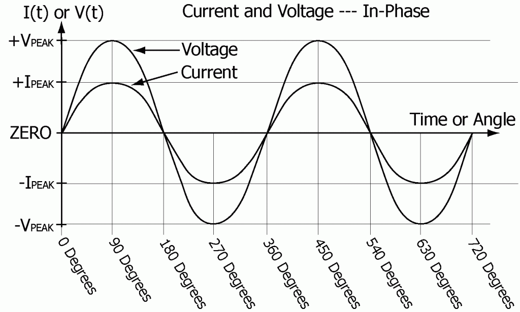
    If you understand this already, Mike, then I apologize in advance. But, I think this comment may be helpful since you asked the question, "Is this a normal transformer?" I took that to mean a normal wave form on the scope for a standard transformer.

    If you hook up one lead on the scope to monitor the voltage across a load and a second lead to monitor the current through a load AND apply an arbitrary varying voltage to the load what you observe will fall into one of several categories. So, to better understand what you would observe, let's further and temporarily add one more restriction or factor to the setup. Let's say that we are applying a "PURE SINE WAVE" voltage to the load.

    Now we turn to the actual possibilities. Let's use the phase relationship to break down the possibilities. From where the VOLTAGE crosses the midline, going from negative to positive to the point where the VOLTAGE again crosses the zero point going from negative to positive represents 360 degrees. It will have crossed going from positive to negative ONE time in between those two points and being a PURE sine wave that point will be at the 180 degree mark. What we are looking for is the point where the CURRENT trace goes from negative to positive and we will express that in degrees, 0, 0 to 90, 90 to 180, 180 to 270, 270 to 360 as a LAGGING current or we can go BACK and say the current is LEADING the voltage. 270 to 360 LAGGING would be 90 to 0 degrees LEADING, etc.

    Now one more simplification. IF this lag or lead is between 90 and 270 we will SAY the polarity of leads on the scope must be somehow reversed and we will physically reverse the leads or use the features of the scope to invert the signal so everything is in the range of 90 to 0 current LEADING voltage, 0 degrees - the voltage and current are in phase, or thirdly 0 to 90 degrees current LAGGING voltage.

    It is hard to explain all this in words without a diagram, but this is the way I think and the way I process information. So, if you follow me, there are really, at this simple level ONLY 3 possibilities and each one has specific meanings.

    First and easiest: "0 degrees" Current neither leads nor lags voltage. The LOAD is functioning as a pure resistor. If there are any capacitors or inductors in the load they are somehow in balance. This is called "resonance" and we don't usually or really care whether or not that is or is not TRUE resonance, we just call it resonance. In the case of "theory" and "science" it accepted on faith that it IS true. Blah blah blah.

    Next: "current lagging voltage 0 to 90 degrees" Inductance is dominant in the load. If you want "resonance" you need to add more capacitance.

    Third: "current leading voltage 0 to 90 (or 90 to 0) degrees. Capacitance is dominant in the load. If you want "resonance" you need to reduce capacitance or "add" inductance.

    That's all there is to it. It doesn't matter what kind of transformer or coil or combination of them that you have. There may be a few "niceties" that could be added to the explanation, but I think they are minor.

    I hope that helps.
    Last edited by BroMikey; 11-06-2014, 06:51 AM.

    Leave a comment:


  • wayne.ct
    replied
    Interpretation of wave forms on the scope

    If you understand this already, Mike, then I apologize in advance. But, I think this comment may be helpful since you asked the question, "Is this a normal transformer?" I took that to mean a normal wave form on the scope for a standard transformer.

    If you hook up one lead on the scope to monitor the voltage across a load and a second lead to monitor the current through a load AND apply an arbitrary varying voltage to the load what you observe will fall into one of several categories. So, to better understand what you would observe, let's further and temporarily add one more restriction or factor to the setup. Let's say that we are applying a "PURE SINE WAVE" voltage to the load.

    Now we turn to the actual possibilities. Let's use the phase relationship to break down the possibilities. From where the VOLTAGE crosses the midline, going from negative to positive to the point where the VOLTAGE again crosses the zero point going from negative to positive represents 360 degrees. It will have crossed going from positive to negative ONE time in between those two points and being a PURE sine wave that point will be at the 180 degree mark. What we are looking for is the point where the CURRENT trace goes from negative to positive and we will express that in degrees, 0, 0 to 90, 90 to 180, 180 to 270, 270 to 360 as a LAGGING current or we can go BACK and say the current is LEADING the voltage. 270 to 360 LAGGING would be 90 to 0 degrees LEADING, etc.

    Now one more simplification. IF this lag or lead is between 90 and 270 we will SAY the polarity of leads on the scope must be somehow reversed and we will physically reverse the leads or use the features of the scope to invert the signal so everything is in the range of 90 to 0 current LEADING voltage, 0 degrees - the voltage and current are in phase, or thirdly 0 to 90 degrees current LAGGING voltage.

    It is hard to explain all this in words without a diagram, but this is the way I think and the way I process information. So, if you follow me, there are really, at this simple level ONLY 3 possibilities and each one has specific meanings.

    First and easiest: "0 degrees" Current neither leads nor lags voltage. The LOAD is functioning as a pure resistor. If there are any capacitors or inductors in the load they are somehow in balance. This is called "resonance" and we don't usually or really care whether or not that is or is not TRUE resonance, we just call it resonance. In the case of "theory" and "science" it accepted on faith that it IS true. Blah blah blah.

    Next: "current lagging voltage 0 to 90 degrees" Inductance is dominant in the load. If you want "resonance" you need to add more capacitance.

    Third: "current leading voltage 0 to 90 (or 90 to 0) degrees. Capacitance is dominant in the load. If you want "resonance" you need to reduce capacitance or "add" inductance.

    That's all there is to it. It doesn't matter what kind of transformer or coil or combination of them that you have. There may be a few "niceties" that could be added to the explanation, but I think they are minor.

    I hope that helps.

    Leave a comment:


  • BroMikey
    replied
    Waveforms

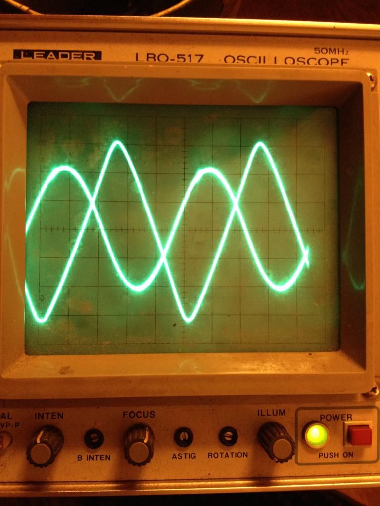
    Transformer wave phasing


    This is the Bi-Toroid wave phasing

    Leave a comment:


  • BroMikey
    replied
    Waveforms and Error

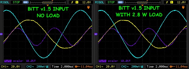
    This should help with puzzling error. This is nothing like a BITT. It is a wave shape that we all have become accustom to for 100 years.


    I don't like that one as well as this one. This one is the wave in a Bi-Toroidal transformer.


    I will be posting wave forms so I can get an idea what others are seeing with the BITT.


    Leave a comment:


  • Web000x
    replied
    Originally posted by BroMikey View Post
    I could be off by 5 percent. Lets say I am off by 10 percent which clearly is not a 65 degree angle. That would still be over 100 percent.


    Mike, I hate it for you but wouldn't get too excited yet. In order for sine wave math to be of any use, it must be in the shape of a sine wave. Your lower scope wave is totally distorted and distorted right in the places that matter most. There is a low dip on the region where power is being returned to the source and high peak when the source is being drained of energy. This dip and peak will totally skew power measurements when using cosine angles. If you were to see this on a scope with math functions, you'd see the area underneath the wave and it would look much different than true sine waves displaces by that same angle.

    Take Luck

    Dave

    Leave a comment:


  • BroMikey
    replied
    Circuit ZERO CROSSING?

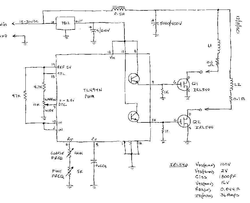
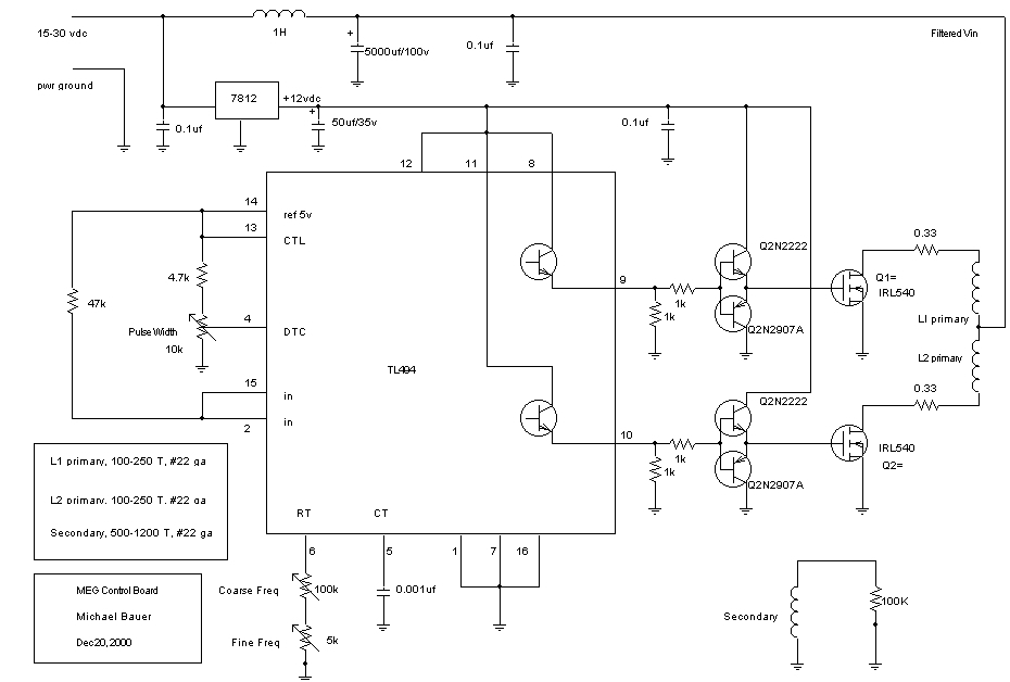
    MEG driver


    Leave a comment:


  • BroMikey
    replied
    What Error?

    I could be off by 5 percent. Lets say I am off by 10 percent which clearly is not a 65 degree angle. That would still be over 100 percent.


    So this is not a normal transformer, wouldn't you agree with that?

    Input 200ma X 8.28v = 1.656 X.42= .70 watts real

    Output 117ma X 6.15v = .72 watts real COP 102percent

    So we can see this is a very low OU system that must be improved upon.

    All before I tune it more, only day one on 60hz.

    C WhadI'm Sayin? Whadja think of that last video of Clean I posted where he puts in half of what he gets out?

    Dave do you have a simple zero crossing circuit I can build?

    Mike


    Originally posted by Web000x View Post
    Mike,

    How are you figuring your phase angle? Do you have a scope function that measures it for your or are you 'eyeballing' it?

    Dave
    Last edited by BroMikey; 11-04-2014, 07:10 PM.

    Leave a comment:


  • Web000x
    replied
    Mike,

    How are you figuring your phase angle? Do you have a scope function that measures it for your or are you 'eyeballing' it?

    Dave

    Leave a comment:


  • BroMikey
    replied
    Doing re-run of figures

    I have some new figures 128 percent all the way down to 60 percent
    Check this page in 5 minutes again and I will have finished the calcs


    Okay here are the low down DOG figures.

    I had originally made a mess of my old calculations yet it seems they were actually right on arrived at wrong. Let's talk about that later but reactive power in caps can give real power figures.

    Here we go, and this time I used 70 degrees COS figuring instead of 75.

    Before tuning with caps

    Input 189ma X 6.64v = 1.26 X.34= .43 watts real

    Output 89ma X 3.29v = .30 watts real COP 69percent

    next set of calculations

    Input 153ma X 4.95v = .76 X.34= .26 watts real

    Output 76ma X 1.82v = .14 watts real COP 54percent

    one more set then I will be back in 5 minutes

    Input 245ma X 9.38v = 2.30 X.34= .78 watts real

    Output 110ma X 5.42v = .60 watts real COP 77percent

    So this is very low. Next I will show figures with caps

    wow wee did I flip out when I hooked up my same caps I used last week. I tuned it last week and the light jumps way up for less power input by far with only a 2-3 degree change in phase angle.

    This calc is for a single cap on the input and one on the output.

    Input 270ma X 9.50v = 2.56 X.34= .87watts watts real

    Output 130ma X 7.60v = .988 watts real COP 114percent

    Now I added one more big cap on the input dropped even more with a 2 degree shift. It doesn't work better loading this BiTT to 45 degrees.

    We must stay at the 70-90 degree range.


    the best ones


    Now I am using 50uf on the input and 35uF on the output with a phase angle around 72-75 so lets say 70 degrees COS is .34 same as before just rephrasing for those who are beginners like "yours truly"

    Input 245ma X 9.62v = 2.36 X.34= .80 watts real

    Output 131ma X 7.70v = 1.01 watts real COP 126percent

    Last calc for today


    Input 200ma X 8.28v = 1.656 X.34= .56 watts real

    Output 117ma X 6.15v = .72 watts real COP 128percent

    So we can see this is a very low OU system that must be improved upon.

    Tuning means a lot to brightening up the output lights and man what a difference.

    Mike
    Last edited by BroMikey; 11-04-2014, 09:29 AM.

    Leave a comment:


  • BroMikey
    replied
    Zero Crossing video

    Here is a video I want to show you Dave. He has a small circuit zero crossing circuit also uses a center tap on the primary.

    https://www.youtube.com/watch?v=cm-YQdfEqBA

    Leave a comment:


  • BroMikey
    replied
    Excuse Me?


    The most important thing BILL A pointed out was that conventional transformers use up or burn up approx 100 percent of what they run on.

    Not so with a BiTT as you well know. BILL did show a 90 degree shift with the secondaries shorted out with a 1 ohm resistor.

    Are you saying if I run without a load, I should get 90 degrees? Well its a new field and I didn't think of that yet. Maybe I better hear more.

    Any other tests you have in mind? Let me know.

    I am speaking in general terms using the same calculations and load resistance, being a set a 5 small lights that won't take more than 120ma no matter how much power you put to them. The voltage climbs after the amps stop rising.

    You see for days I had been making calculations using wrong methods, no one inquired or asked. Everyone just assumes everything or don't have time, to busy whatever I am learning by watching the Thane videos, the Bill A video, the Mr clean Video's.

    I am a green horn, can't run a scope worth beans, never run a reactive COS calculation til today. I have no idea what is in other peoples minds unless they talk and I sure don't know what I am doing.

    Thane does, Bill does, and now so do I.

    A special thanks to those guys.

    BILL A had a figure of 78 degrees so 15.75 watts was measured X .20 = 3.2watts I think is all it used out of the 15+ watts.

    You see I was just using raw numbers and you experienced guys didn't bother to check me out to see if I was doing it right

    You guys should know better than that I'm gonna catch up soon.

    Mikey You are Right DOG here in this video
    httphttps://www.youtube.com/watch?v=QHZAzlqEKns://


    Originally posted by Dog-One View Post


    Then your "normal transformer" is a piece of crap. You should get very near 90 degrees shift when the transformer is unloaded, because all it is doing is free-wheeling as an inductor--the secondaries aren't doing anything, not even connected.

    Then, you can connect a small load and slowly increase it while watching the phase shift decrease. It's a good idea to note how much load you have when the phase shift drops half way to 45 degrees.

    Probably a good idea to do some testing with just a plain power transformer and make sure your instrumentation is correct and that your readings make sense. Do this before you make any comparisons against an SFT.
    Last edited by BroMikey; 11-04-2014, 06:31 AM.

    Leave a comment:


  • Dog-One
    replied
    Originally posted by BroMikey View Post
    Well i am getting a 75 degree shift on this BiTT over here. It is anything but normal. A normal transformer shows a shift of a few degrees and thats all you are ever going to get out of it.


    Then your "normal transformer" is a piece of crap. You should get very near 90 degrees shift when the transformer is unloaded, because all it is doing is free-wheeling as an inductor--the secondaries aren't doing anything, not even connected.

    Then, you can connect a small load and slowly increase it while watching the phase shift decrease. It's a good idea to note how much load you have when the phase shift drops half way to 45 degrees.

    Probably a good idea to do some testing with just a plain power transformer and make sure your instrumentation is correct and that your readings make sense. Do this before you make any comparisons against an SFT.

    Leave a comment:


  • BroMikey
    replied
    Normal Transformers

    Originally posted by Web000x View Post
    I started off with a turns ration of (primary:secondary) 62:100, then 38:100, then 24:100, then 24:162. None showed anything other than conventional transformer actions.

    Dave
    Thanks Again Dave

    Thats a lot of winding coils this one that one and nothing, AAA?

    Well i am getting a 75 degree shift on this BiTT over here. It is anything but normal. A normal transformer shows a shift of a few degrees and thats all you are ever going to get out of it.

    The way it looked over here at first before I add the cos value was 3X current going in. Then when I figured the 75 degree shift things change.

    For instance without and caps for tuning I got 8.2vac X .3amps = 2.46 watts going in. That is what it looks like if you don't use the COS. In my case with the BiTT the COS of 75 degrees is .26 but with a normal transformer the COS of 15 degrees is .97 that is a huge difference.

    My 2.46 watts X .26 = .64 watts is real only the large portion keep circulating.

    On the other hand a 2.46 watt X .97 = 2.39 watts real power used up out of 2.46 watts. This is a standard reading for a conventional transformer.

    My output with no tuning is 4.5vac X .120 = .54 watts real used up without even trying that is 85 percent efficient. I have no tuning, poor coupling, not high frequency and still right off the bat I am 85 percent.

    Totally incredible. Just generalizing from previous figures with poor coupling no frequency just tuning I see over 100 percent.

    The previous numbers were all good except the amp reading on the input was 3X higher than I thought then I turned right around and cut that value into quarters so my figures were good as far as I can tell. Just arrived at wrong.


    I will redo all of the figures. a 75 degree shift is .26 meaning if I input 1 watt I am only using approx 1/4 of that so .26 or 26 percent is used, the rest it sent back for recycling.

    For every watt your standard transformer runs on uses up 96 percent of that.

    So my BiTT needs work sure but will one day give me a 1:4 ratio something a conventional transformer can never do with this experiment.

    Wow Wee is all I can say.

    See before I was thinking 85ma was on the input when it was more like 300ma. So before I was saying 9.6vac X .085 = .815 watts

    instead it should read 9.6vac X .300 = 2.88 watts but now I use the .26 COS calculation that I never used before so this is less on the input than I thought. The input would be 2.88 X .26 = .75 watts when before I thought of the input as .815.

    So you see I am getting 125 percent after all.

    I will make sure, don't get me wrong I am pretty sure like before but this time maybe I won't be as far off with the calculations.

    Mikey
    Last edited by BroMikey; 11-03-2014, 01:01 AM.

    Leave a comment:


  • Web000x
    replied
    Originally posted by BroMikey View Post
    Hi Dave

    The setup you have is 6 to 1 ratio or higher. Maybe try 3:1 windings ratio like BILL A is using. I mean i think he had 40 turns and two 120 turn or is that feet? I'll put 10:1 the ratio is off

    Mikey
    I started off with a turns ration of (primary:secondary) 62:100, then 38:100, then 24:100, then 24:162. None showed anything other than conventional transformer actions.

    Dave

    Leave a comment:


  • BroMikey
    replied
    6+ to one ratio

    Hi Dave

    The setup you have is 6 to 1 ratio or higher. Maybe try 3:1 windings ratio like BILL A is using. I mean i think he had 40 turns and two 120 turn or is that feet? I'll put 10:1 the ratio is off

    Mikey


    Originally posted by Web000x View Post
    Here is a less than awesome quality video showing my setup. I tried using the HD function but it wouldn't load so I had to settle for standard quality.

    https://www.youtube.com/watch?v=7mCx...L6cdsupqwo9-Hg

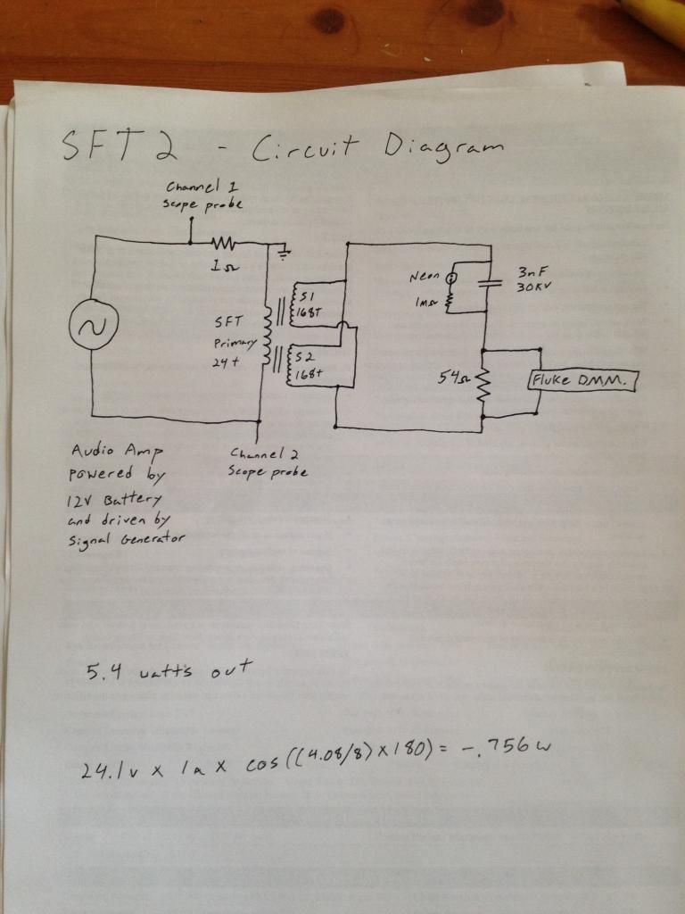
    Here is my schematic:


    Dave

    P.S. I made a mistake in a previous post saying that my turn ratio was 1: phi^3. I was mistaken. It is 1: phi^4, or 24:162. The schematic also wrong. It says 168 turns on the secondaries, but it should say 162 turns.

    Leave a comment:

Working...
X