Announcement

Collapse
No announcement yet.

Bi-toroid Transformer of Thane C. Heins

Collapse
X
 
  • Filter
  • Time
  • Show
Clear All
new posts

  • Dog-One
    replied
    Originally posted by BroMikey View Post
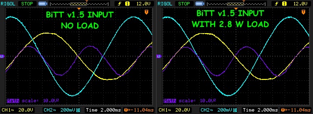
    1.5 version no change on input at 2.8watts output with advanced Scope shots
    Taking with Paul and Jim the other night, two things we need to investigate:

    1. The air gap in the cores.

    2. The optimum load.


    Both of these guys are hot to look into this device. They both see the similarities to the SERPS device and feel this may be the avenue to pursue to give us the same effect without all the switching electronics.

    The concept Jim mentioned relates a motor/generator with a transformer and he knows how to make a motor be only a motor and a generator be only a generator. The concept is directly applicable to a transformer as well.

    I need to get winding coils...
    Leave a comment:


  • BroMikey
    replied
    BiTT working at 60hz

    1.5 version no change on input at 2.8watts output with advanced Scope shots


    https://www.youtube.com/watch?v=2aVN08CYPi4


    Last edited by BroMikey; 10-25-2014, 09:27 AM.

    Leave a comment:


  • BroMikey
    replied
    Iron Cores

    I posted that Video a while back and at that time I sort of berated this guy for not following instructions. He may be a well meaning feller but the fact remands that he is powering a load of light bulbs and THIS is his goal, Not finding OU.

    Thanes goal is different.

    These guys are easy for me to see right through. Stick with me and we won't be getting any wool over anyone's head I wonder sometimes about why people do this stuff.

    Here he is with an iron core, no extra long winding to compensate for his ferrite or metglass, because he has none. His demonstration shows a conventional iron core three phase transformer from right out of a high energy lighting system. Or something like it of three phase operation.


    He never once fooled me with his immaculate layout and fine meters.

    I'de rather go watch an old John bedini video .

    Let's refresh ourselves that as Dog-One had pointed out when I was about to power up that more wire per coil was needed. Why? Because the ferrite do no conduct the same or saturate the same as iron.

    Following instructions is something this guy did not do.

    The proper way to use the 93 volts to power his lights is to first follow Thanes instruction using the right core material. Next 3-4 times the length of wire as what would be required with a standard iron core like he has.

    You can't kid and old kidder That guy is barking up the wrong tree if he wants me to believe his setup is spot on to Thane Heins.

    Thane Heins spent the money on noncrystalline Permalloy tape as it is referred to and 4 times the copper for 1/10th the power out. Thanes very dim light looked ridiculous to some I suppose yet he had the effect.

    Many experimenters want to call their experiment by another mans setup or a replication they call it, then don't do anything the same as the original.

    That is what the guy in this video did. I don't know what was in his head. Some might venture to say that he is getting paid to propagate disinformation. I don't think he is doing it for money, I don't think he grasp the idea. He is still inside the old iron box

    @Dave

    Did you replace your wire wound resistor with a carbon type. And did you loose your phase angle? Time for tuning? What happened?

    Mikey


    Originally posted by Web000x View Post
    So this guy made a video that really illustrates with better test equipment exactly what I have been seeing. https://www.youtube.com/watch?v=j-dZj4-PU9s

    I'm not doubting the reality of OU, maybe I'm missing something with my experiments...

    Good Luck,

    Dave
    Last edited by BroMikey; 10-25-2014, 07:57 AM.

    Leave a comment:


  • Web000x
    replied
    So this guy made a video that really illustrates with better test equipment exactly what I have been seeing. https://www.youtube.com/watch?v=j-dZj4-PU9s

    I'm not doubting the reality of OU, maybe I'm missing something with my experiments...

    Good Luck,

    Dave

    Leave a comment:


  • BroMikey
    replied
    Bi-Toroidal Transformer

    I am not ready for the video yet but it will come soon I promise. That would put me under Unity. Or below.


    One coil of the secondaries is round and the other is triangular therefore i can only run one core instead of two in each primary to secondaries(2).

    When I begin running and amp with frequencies in the khz I will have both secondaries in triangular form and using more core material.


    As can be seen in this shot the link between secondaries has 3 flyback C-Cores added together as one, under the PVC tape.


    Tuning is done with a 35uf 270vac cap in the secondaries and a 23uF in the primary side.

    Here is a small UPS circuit.


    I will use it to power the circuit using batteries so isolation from the scope is better and I can use DC amp meters to monitor the power draw. Later it might be possible to send some power back to the battery to self run the system.


    The circuit is very small yet it can run a 50watt load with great ease.

    This next picture is of one of my scopes and one generator.


    Be encouraged free energy is here We just need to work day and night to make it more practical.


    Mikey


    Originally posted by Web000x View Post
    I'm just trying to help you by looking at your test procedure to see if there is any noticeable error. Trust me, you don't want to run around telling everyone that you've achieved OU only to have to retract that statement a few weeks down the road. Having done it more than once, I can tell you that it sucks. If your numbers are correct, then there is something outside of convention going on in your circuit. I'm not saying your wrong, just that I want to be sure that you are right.

    If your primary core is saturating at all, your secondary waveform will be distorted.

    Forgive me if I sound slightly skeptical, but having investigated the Bitt on a few different occasions with no positive results, I'm feeling the need to see data and ask questions.

    Dave
    Last edited by BroMikey; 10-31-2014, 06:58 AM.

    Leave a comment:


  • BroMikey
    replied
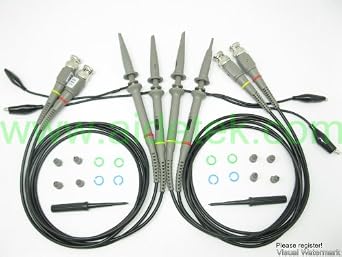
    Probes

    Got 4 more last night all the same brand new.

    I will take some shots soon also and show my UPS circuit as well.


    Mikey

    Leave a comment:


  • Dog-One
    replied
    A very excellent video to watch and understand. I good four channel scope and you shouldn't need any differential probes.

    My old analog BK Precision scope doesn't have math functions, which is why I had to get a differential probe.

    Leave a comment:


  • BroMikey
    replied
    Scope Probe

    Here is one of the 2 scope probes I got tonight. These are good ones.


    TPI M20 10X Scope Probe, 2.0 meter 250Mhz


    https://www.youtube.com/watch?v=SUVpRVI06cc

    Mike
    Last edited by BroMikey; 10-24-2014, 07:34 AM.

    Leave a comment:


  • BroMikey
    replied
    Phase Angles

    Yes that helps a lot Dave.

    Now I have something to go by that is for sure when it comes to knowing exactly what to look for on a scope. This is what I had originally gotten out of the Bill A. video and the Thane video's.

    Also I was sure you would say my 1 ohm wire wound would be okay at the lower frequencies.

    I know this is a low powered test that to many is meaningless but some of us know better.

    I am browsing probes.

    Mike

    Leave a comment:


  • Web000x
    replied
    Originally posted by BroMikey View Post
    I understand completely Dave.

    I knew this would become the issue especially with a beginner like me.

    it is a pain to think you found something only to to have to take it all back. This is why many experimenters will not give figures. Either they are afraid of being wrong down the road or called names by their buddies. still I think it is worth it to sharing more specific data.

    I am moving to the scope. Do you think a 1ohm wirewound would produce enough inductance at 60hz to throw off the measurements?

    I want to do things proper. I can show a shot of what the waveforms look like and you gentlemen use to looking at a scope can tell me what you think.

    I have been looking at the Bi-toroid video's over and over. The scope shots everything. I am not so accustom to waveforms like these. It seems like there are 3 waveforms 1 voltage 1 current and 1 power wave.

    I have not decided if those cheapO probes are worth the money yet.

    Do you recommend a place to buy probes you know are decent?

    I don't want to but junk that sends me back again and wondering if my reading was compromised.

    The way my HP 54100D works is you have these pods that slide into the front of the machine and I have plenty to work with. I have a 1ghz pod with probe. Maybe two.

    I have several of what might be called a general purpose lower frequency pods as well but even though I have 4 slots the machine is only a 2 channel.

    I don't see anything wrong with proving this out one way or another and this could be done best with some accurate scope measurements.

    This is something I have always wanted to do. However I have never had anything to compare my scope shots with that make sense to me. Now that I see waveforms of voltage and current I have something to compare.

    Yet when i listen to everyone talk about the mystery of waveforms I makes me think that I could get everything correct looking on the scope and still not be anything out of the ordinary.

    You see in the demo we are shown power factor in relation to leading and lagging or that voltage/current synchronicity is 1 while leading current 90 degrees is 0. Yet when I hear discussions about this it seems that even if a person gets a 90 degree shift they don't automatically have it working.

    See what I mean? It doesn't make any sense to me. If it is one way it can't be the other and round and round we go with no definitive answer.

    Either it is or it isn't all based on this 90 degree shift or am I a raving lunatic ?

    I need to be able to have a more absolute goal. Is it a 90 degree shift that I need?

    Mike
    At 60 Hz, 1 ohm wire wound resistors should be fine. My wire wound resistance measurements would yield this, 2*pi*60*15uH = .006 Ohms. That is nothing compared to your 1 ohm of real resistance. 0.006ohm/1ohm = 0.6%, not enough to count on rough calculations.

    No, I can't speak on probes. I went cheaper than I'd wished. Spend a few dollars and get some that are worth more than $10 each. Don't go nuts. I still get my waveforms right with my cheap ones, but the quality of the probe structure kind of sucks.

    A phase shift of 0 degrees means that your voltage and current are in positive phase together, you are turning ALL of your electrical energy into kinetic energy of some sort, heat, magnetic repulsion, or radiation. You get none back.

    A phase shift of 45 degrees means that you are dissipating a bit less kinetic energy and getting a little more back instead. This would act to lessen the load on a generator motor.

    A phase shift of 90 degrees means that your voltage and current are existing in a relationship where there are equal and opposite power magnitudes. This means that the power you put in is the power that gets returned. This would act as a NO LOAD situation on a generator. The magnetism expended is the same as the magnetism returned. The motor/generator principles are in perfect balance.

    A phase shift above 90 degrees means that you have more energy being returned that you put into the system. THIS WOULD BE FREE ENERGY. A system that returns MORE than you injected.


    So you can see that our goal is 90 degrees or above. If you were to have a generator that could run at a 90 degree phase angle, you could effectively duplicate that generator coil many times and never really 'load the motor'. It would be seeing a no load condition on all additional generator units. This is where you'd siphon the energy and send it back to the prime mover. A looper.

    If you had a phase angle of higher than 90 degrees, the generator would be acting like more of a motor. This is pretty self explanatory...

    There can also be situations where you might have a power factor of less that 90 degrees but still be obtaining OU. You just have to know how to make those calculations. Know how to use the Volts RMS * Amps RMS * Cosine(Phase Angle) = Watts formula as well as how to calculate the power dissipation in the secondary. Then do the Pout/Pin calculations. This one gets tedious...

    Hope this helped.

    Dave
    Last edited by Web000x; 10-23-2014, 04:16 PM.

    Leave a comment:


  • BroMikey
    replied
    Retracted

    I understand completely Dave.

    I knew this would become the issue especially with a beginner like me.

    it is a pain to think you found something only to to have to take it all back. This is why many experimenters will not give figures. Either they are afraid of being wrong down the road or called names by their buddies. still I think it is worth it to sharing more specific data.

    I am moving to the scope. Do you think a 1ohm wirewound would produce enough inductance at 60hz to throw off the measurements?

    I want to do things proper. I can show a shot of what the waveforms look like and you gentlemen use to looking at a scope can tell me what you think.

    I have been looking at the Bi-toroid video's over and over. The scope shots everything. I am not so accustom to waveforms like these. It seems like there are 3 waveforms 1 voltage 1 current and 1 power wave.

    I have not decided if those cheapO probes are worth the money yet.

    Do you recommend a place to buy probes you know are decent?

    I don't want to but junk that sends me back again and wondering if my reading was compromised.

    The way my HP 54100D works is you have these pods that slide into the front of the machine and I have plenty to work with. I have a 1ghz pod with probe. Maybe two.

    I have several of what might be called a general purpose lower frequency pods as well but even though I have 4 slots the machine is only a 2 channel.

    I don't see anything wrong with proving this out one way or another and this could be done best with some accurate scope measurements.

    This is something I have always wanted to do. However I have never had anything to compare my scope shots with that make sense to me. Now that I see waveforms of voltage and current I have something to compare.

    Yet when i listen to everyone talk about the mystery of waveforms I makes me think that I could get everything correct looking on the scope and still not be anything out of the ordinary.

    You see in the demo we are shown power factor in relation to leading and lagging or that voltage/current synchronicity is 1 while leading current 90 degrees is 0. Yet when I hear discussions about this it seems that even if a person gets a 90 degree shift they don't automatically have it working.

    See what I mean? It doesn't make any sense to me. If it is one way it can't be the other and round and round we go with no definitive answer.

    Either it is or it isn't all based on this 90 degree shift or am I a raving lunatic ?

    I need to be able to have a more absolute goal. Is it a 90 degree shift that I need?

    Mike

    Leave a comment:


  • Web000x
    replied
    Originally posted by BroMikey View Post
    Hi Dave

    I thought I was very clear about the waveform. The waveform is straight out of the wall then to a Variac then to the circuit above.


    This is pure line sinusoidal power coming from the utility.


    It is 60hz. The video I put together will have anything as you suggested DAVE. however the diagram is all we need to understand the test procedure.

    In the previous post I state that the meters are in series with the loads at 60hz. what did I miss? I mean I can do a video but the diagram is more important than a guys with wires on a table reading meters.

    Okay but want to do a video anyway.

    My setup is a B-Toroid humm I thought I said that.

    Okay let me ask you again.

    What are your conclusions based on the data?

    That the meter is not reading right?

    Because the meter is only designed for wall current?

    Humm.. well that is what this is, it's 60hz.

    I can't imagine why it must be a false reading of some kind.

    A bad meter hey?

    Mikey
    I'm just trying to help you by looking at your test procedure to see if there is any noticeable error. Trust me, you don't want to run around telling everyone that you've achieved OU only to have to retract that statement a few weeks down the road. Having done it more than once, I can tell you that it sucks. If your numbers are correct, then there is something outside of convention going on in your circuit. I'm not saying your wrong, just that I want to be sure that you are right.

    If your primary core is saturating at all, your secondary waveform will be distorted.

    Forgive me if I sound slightly skeptical, but having investigated the Bitt on a few different occasions with no positive results, I'm feeling the need to see data and ask questions.

    Dave
    Last edited by Web000x; 10-23-2014, 03:22 AM.

    Leave a comment:


  • BroMikey
    replied
    Waveform

    Hi Dave

    I thought I was very clear about the waveform. The waveform is straight out of the wall then to a Variac then to the circuit above.


    This is pure line sinusoidal power coming from the utility.


    It is 60hz. The video I put together will have anything as you suggested DAVE. however the diagram is all we need to understand the test procedure.

    In the previous post I state that the meters are in series with the loads at 60hz. what did I miss? I mean I can do a video but the diagram is more important than a guys with wires on a table reading meters.

    Okay but want to do a video anyway.

    My setup is a B-Toroid humm I thought I said that.

    Okay let me ask you again.

    What are your conclusions based on the data?

    That the meter is not reading right?

    Because the meter is only designed for wall current?

    Humm.. well that is what this is, it's 60hz.

    I can't imagine why it must be a false reading of some kind.

    A bad meter hey?

    Mikey


    Originally posted by Web000x View Post
    I think it might be due to the fact that there are a lot of unknowns. It would be really helpful if you could make a short video showing your set up and line of logic for taking measurements. If you aren't getting perfectly sinusoidal current waveforms, your amp meters might not be reading correctly. Scope shots are pretty important. Show us what you're up to and I'm sure you'll get the response from Farmhand that you seek..

    Dave

    Leave a comment:


  • Web000x
    replied
    Originally posted by BroMikey View Post
    It's awful quiet here

    Mike
    I think it might be due to the fact that there are a lot of unknowns. It would be really helpful if you could make a short video showing your set up and line of logic for taking measurements. If you aren't getting perfectly sinusoidal current waveforms, your amp meters might not be reading correctly. Scope shots are pretty important. Show us what you're up to and I'm sure you'll get the response from Farmhand that you seek..

    Dave

    Leave a comment:


  • BroMikey
    replied
    Quiet Time

    It's awful quiet here

    Mike

    Leave a comment:

Working...
X