-
To any of you that read an excerpt in the previous post about number of secondary turns and lower frequency. I've retracted that statement and omitted it from the post. I'm still not sure of the direction to go on primary to secondary turns ratio. -
I'm seeing good results at around 80 kHz when the secondaries are wired in series, resonating with a 10 nF series capacitor, and powering a small load such as a 3 volt lamp. This is where I obviously see incandescence coming from the secondary load while also seeing a negative power factor on the scope. The phase shift is obviously greater than 90 degrees. Still waiting on new, identical scope probes to arrive in the mail. But from the battery of tests I threw at these probes, I'm pretty sure what I am seeing is legitimate.Originally posted by Dog-One View Post
I'm still not sure how to measure my output in my secondaries to the fullest extent possible. I can find the resistive wattage with no problem, but I have a significant amount of heat emanating from my series resonating capacitor. I haven't quite wrapped my head around what I need to do to calculate the conductive losses in the dielectric material in the capacitors. It appears that the heat is actually coming from the dielectric like Dollard has spoken about. If anybody has any ideas, let me know.
I'd love to throw a parallel resonating capacitor on the primary tuned to the frequency that my secondaries resonate at. Ideally, I'd be able to get the oscillations started with a quick make and break power switch sequence and then let the oscillations grow until it burns itself up or falls out of resonance due to total saturation. This system is very dynamic. It is difficult to account for the many variables of varying inductance to get it right on the first try. I'll keep at it. Hopefully we can keep the circuit simple.
As far as your idea about secondary windings turn ratio, I think it is an interesting concept, but can't help but to think that you might be losing efficiency. By skipping turns on the primary toroid, you are effectively lowering your EMF applied to the secondaries. It just seems to me that you would want your primary and secondaries to be as fully connected and fully disconnected as possible, if that makes any sense.
I encourage everybody to pick up some of the 3r1 cores that Dog One referenced in the above quote. They are less than 3 bucks a pop and they do indeed show what appears to be power flowing back to the source. I spent way more on mine than that... This is what I've needed. Something I can study which will show me the way. It's pretty inspiring to see it manifest on your bench.
Good Luck All

DaveLeave a comment:
-
magnetic flux simulation software
For these types of transformer windings it might be necessary to turn the formulas for expected electrical behaviour from electrical values parameters to magnetic flux parameters.Originally posted by Dog-One View Post
why?
using 1 wire for winding around both the black core and the small one and then the same for winding for the small core only will create more than a change in transformer rating. the wire between the black and the small core wil create another kind of influence to the magnetic flux.
looking for a software based on magnetic flux calculations in a multi-core system could be a good idea for that reason.Leave a comment:
-
FerroXCube 3R1
With Dave having success with this material, I feel it pertinent to reference it here for others to follow along:

I'm assuming these are the ones:
TN36/23/15-3R1 - FERROXCUBE TN36/23/15-3R1 - TOROID | Newark element14 US
What frequency are you running at?Secondaries - 2x 100t 26AWG
Primary - 38t 23AWGLeave a comment:
-
Demo
Agreed Dog-One
Thanks for the transformer winding calculation I need to brush up on figuring instead of just using what I have.
The demo is Thanes come on to propose to other companies who may research and develop this stuff. We don't have a $100,000. However $200 might get enough tape to make any SHAPE but there is still the matter of nano-crystalline compatibility based on calculation as you have pointed out.
What the video does do is gets the average Joe experimenter off of the chalk board and into the game room where coils are wound. While $900 is a bit steep for our pocket book especially if it lands in the pile as a failed project afterwards, we might rerun some of those figures til we turn the tables around like Bill did in using standard low cost cores.
Still in all without circuits we can explore whether or not the principle works and while the input is a few watts for all of that core material expense the output is twice.
This beats the one watt challenge like the dead horse that it is.
Then if we are not getting enough to be practical later each one us could take the same core material we got our hands on for the price we can afford and feed it with AC ofa higher frequency. So we are not out the money either way we go.
When I went to Micro-metals one time to get a Bob Boyce core or two they only had one that works in that frequency band. So there isnt that many out there.
But what you are talking about to true, raising the frequency on the same core with the right windings could give a 100X price to output ratio like the switch mode industry operates.
Still the demo is a delight because I can go into the lab at anytime and prove this out for myself with wall current.
The formula is good to find Dog-One with so many around it is sometimes hard to decide witch approach is enough for our design.
If you are this good with the math I would say you are a great asset to our transformer builds. Thane said in the video he would always get at least twice as much power out for the same input of a conventional transformer using the Bitt even at 60hz.
This is very encouraging.
I have a pile of flyback transformer cores I am working on to get them out of televisions. People give them to me (The old ones) so resently I have learned not to break them by cutting of each side of the cores putting a bandsaw blade along side or flush with the cores making a cut on each side.
The core just fall out.
This material is high frequency material so I think it will work but like I said I do things to save money if I can and I am not so sure it will be the most optimum.
Getting the Frequency up and thus the power levels per unit cost whatever the output voltage is should be a great first step with enough to loop the thing even with many losses.
Mike Last edited by BroMikey; 10-04-2014, 05:18 AM.
Leave a comment:
-
Understand when you wrap a primary core, the number of turns is directly related to this formula:Originally posted by BroMikey View Post
Turns = VoltsRMS / 4.44 / meters^2 / Hertz / Tesla
Tesla (working flux density of the core material) being in the neighborhood of 1.0 to 1.7.
I think I mentioned this, I requested two quotes from suppliers that can manufacture custom cores and they were both asking about 900 dollars to build me such a core. If I truly thought I could get 1000 watts out of such a transformer, I would have made the investment already. Notice Thane's load, a dimly lit 2 watt bulb. Pretty hard to justify.
I do think Thane's concept is workable, I just don't know that we can acquire the materials to make something viable without a serious financial investment. Which is why the Bill Alek derivative makes more sense--we can get commercially available toroids and C-Cores for considerably less money. And if we run at higher frequencies there will be electronics involved, but we all see how the progression of linear power supplies morphed into switching power supplies, so we can follow the same path. Maybe in the end we can have 1000 watt, 10% PF devices that are relatively small and inexpensive. The goal is right there just within reach if we work for it.Leave a comment:
-
Large coil windings 60HZ 169 volts AC Input Side
Straight AC coming off the wall Thanes Video.
Look at the size of those windings. 169 volts AC on the input side.
https://www.youtube.com/watch?v=x7JDElxCyX4
No Frequency just AC but his cores are high frequency response type.

MikeLeave a comment:
-
Sphere
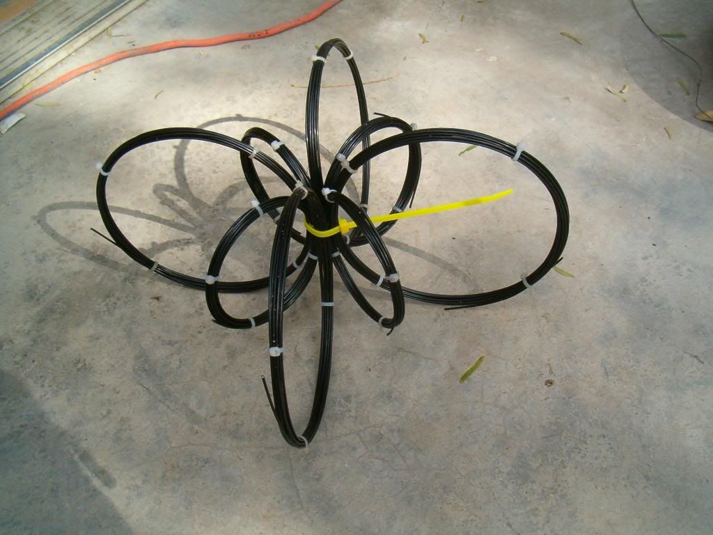
Hi Dave45, That pic is very similar to my spherical magnetic rotor I made.
The magnetic fields off of mine were equal strength at any location of the arc ,I wonder what the fields would be like if you put power into that .
Thanks for the idea I use magnets , but never thought of using electro-magnets.
artv
P.S. Is a coil considered an electro-magnet if it doesn't have a core?Leave a comment:
-
If you want to build a transformer type device go for the gusto do something different. I would advise a magnetic shunt be incorporated.
Center coil (primary) resonant tank circuit
Outer coils series resonanceLeave a comment:
-
101 Winding Instructions
Hey Dog-one
Good Idea. I'll never forget how I have ripped the windings out of the MOT and kept watching the volt meter as I added turns. It turns out most MOT have a ratio that when I put 1 turn I get 1 volt more so if I am making a 24vdc charger I use 36 turns or 36vdc no load.
Watching a meter is the only way sometimes.
The way I am going to do this is fill my core material so it is a tight transformer and whatever comes out will go to capacitors to charge batteries.
This is why i am thinking along the lines of a car audio amplifier so I can drive it with DC 12 volt battery. Then if my voltage is 50vdc (Lets just say it is) on the output I can charge two 12vdc batteries dumping them with 50 volts.
Or when the primary side goes down I can use a battery changer to swap out the half dead one for a full one.
I want to close the loop one way or another (Have not decided) so I have a self contained battery charger like the ELECTRIC BIKE companies are doing.
It's not like we are breaking new ground here. I just want something practical and those guys get all of the credit.
Mike PS does anyone know why it does or doesn't matter if CCW and CW makes any difference on these Bitt's???? Talk to me somebody.
Originally posted by Dog-One View PostLeave a comment:
-
More on turns ratio...
I see now what needs to be done to get this to work as optimally as possible.Originally posted by BroMikey View Post
First, we need to decide the step-up voltage ratio we want to have. This is easy and we can do it without even having the Back EMF core. We simply wind the primary, connect it to our amp and then add a secondary winding, adding turns while watching a volt meter until we have the target voltage we are after. While doing this, we need to adjust frequency to get the value that provides the best coupling we can find. This will give us the turns ratio for both sides of the primary and the operating frequency.
Second, we strip off the secondary we just wound and keep track of the number of turns we had, we will need this value later.
Third, we wind the Back EMF core only with two windings using the number of turns we just found in step two. 1 : 1 ratio. Connect one side to the amp and look at the voltage coming out the other side. Here we leave the frequency fixed that we found in step one. Then we add or remove turns equally from each side of these two windings to find the max voltage, best coupling. Now we should know the correct number of turns for the Back EMF core.
Fourth, we strip off the windings from the Back EMF core and begin to wind the complete SFT using the values we found previously. To do this we look at the two turn values we found in step two and step three. Whichever value is lesser, that will be the count of turns that go around both the Back EMF core and the primary core. Now we take the difference of the two values; this will be the number of additional turns that go around either the primary core or the Back EMF core. If the value in step three is larger than the value we found in step two, the remaining turns will go on the Back EMF core. Otherwise we put the remaining turns on the primary core.
Fifth, duplicate the other secondary exactly the same as you did in step 4.
Doing this should result in having an SFT that has optimal coupling throughout all the cores, give or take. It's possible that additional tuning will be necessary, but I would expect this technique to get you pretty close. I'll be doing this technique myself when my cores arrive. Which reminds me, I need to check and see if I have a tracking number...Leave a comment:


Leave a comment: