
Originally posted by BroMikey
View Post
-
Originally posted by Dog-One View Post
Hey Dog-One
Web000x does indeed have something that is not ordinary.
Getting in on the ground floor is wonderful but we have a long way to go. For instance just like we all took a closer look at the Bill A. rep of the Thane H. Bitt and saw that maybe just doing winds and cores any ole way wouldn't work, maybe we should look closer once again.
Again I am going to assume that Bill A. made his video in a way that makes this easy for the experimenter to get results.
Okay so starting from that premise how many times do you think Bill wound a set of coils for a given inductance? Some of our mathematicians should be helping with the coil perimeters shown in the demo.
Gentlemen math plays in to this we can't throw out all of our training.
Questions need to be asked. What is a good ratio, is it 1/4 wave? Primary to secondary?
Is the ratio based on inductance? Where are the figure crunches?
We are getting proper C-cores and this is first base.
Second base is realizing that a target frequency is 1-3khz at the wire size and inductance that was graciously supplied to us.
We can figure out these general values and should be looking at that demo for our introduction.
It takes time and money to wind and rewind and over again. Bill has given us the coils induction. Also judging by the approx coil diameter we have enough to get close to Bill's values.
We can shoot in the dark just like he did if we want but I think Bill's goal was to show a simple generator, to simple amp at the said frequency plus coil ratio's to help us get where he is in a lot shorter time.
Why else would we be privy to the inductance values?
Which way should we hook the two secondaries together? Should we cross wires, or in series or short them.
The demo shows two wires coming out of a four wire set.
Does one connection path work better than the other at the said frequency?
These and many more should be the questions we take with us after random winds.
Are they to be wound clockwise or count clockwise? Or one clockwise and the other counter??????? Or both counter Clockwise? In the northern hemisphere?
Either way we wind it, this is far above any transformer that I have ever witnessed and well worth the excitement. I have wound many transformer and this BiTT is the first transformer I have ever seen that shows such wild scope shots.
Totally awesome and new technology takes my breath away when see it for myself. I have never seem anything like it before.
MikeLast edited by BroMikey; 09-27-2014, 08:38 PM.Leave a comment:
-
Scope confusion
Originally posted by Farmhand View Post
Looks like you better get a real Bi-Toroid wind job huh? Those choke inductors show a wave former that is so normal.
It is like saying Joe over here has a fast car and you can't figure out why your Yugo 1 liter car can't catch up.
Your scope shot is nothing like Dave's.
I recommend you take out 30 or 40 minutes and wind the 3 stage transformer and start there. Then after you make the baby step you can loop it back.
The thing I have noticed about your communications are that you pose yourself as the ultimate all knowing who's goal is to stop everyone who is thinking of trying a given experiment.
If you won't make any effort to add constructively and will only spend time throwing water on our fire, what does that say?
I will tell you what is says. It says you are afraid that this stuff works you and the entire scientific world are a bunch of stammering BOOZOO'S.
On the contrary, your expertise is invaluable but comparing inductor laying by magnets or whatever is a dishonest approach to the BI-Toroidal.
After I am done showing everyone how you have only the desire to put yourself above everyone calling us fools under your breath for even trying, very few will listen to your lies.
Don't come here using trickery. I don't trust you Farmboy. When you show me a setup or anything that shows that you are trying to go OU (OVERY THE LAST 10 YEARS) then I will change my mind.
Til then you are nothing but a liar who will not try this work and only goal is to put a stop to anyone trying.
This is evidenced by the way you demand that the beginners loop it all back to save the world before they even tuned their boards.
You are very smooth and love disruption. I doubt you will be around much longer Boy.
Mikey PS I'LLL BEEE BACK!!!!
Leave a comment:
-
I have enough of these cores to make three more transformers. I'll try some different configurations when time allows.Originally posted by Dog-One View Post
There is no point to showing amplifier power draw as it doesn't seem to be reflective of reactive power sent back to the amp. The amp's current draw seems to be directly related to the positive half of the power wave and does not even respond to reactive power sent back. This will have to be sorted out with a motor/rotor configuration. However, not sure how I will get to my target frequency of 80kHz with a mechanical setup. That would be a 1300 magnet rotor at 3600 rpm. Hopefully I can tune this down to a more manageable sweet spot.
DaveLast edited by Web000x; 09-27-2014, 03:50 PM.Leave a comment:
-
Now that would be the whole point to this endeavor, wouldn't it? Right now, I can confidently say that this circuit is extremely inefficient due to my power supply being an audio amplifier. The amp doesn't seem to care much about reactive power being returned and continues to consume power from the battery. However, if this were a mechanical alternator/generator, I might see reduced drag and increased rpms on the rotor. The point of me posting these pictures was not to claim OU, but rather show people that I am getting a novel waveform that falls in line with what AuroraTek and Thane Heins showed and to encourage more experimentation. I worked with a lot of magamps back around the time I was involved with Eric Dollard, but never did I see any negative power factors, until now.Originally posted by Farmhand View Post
I don't understand how you came to the conclusion that your circuit was not novel when you clearly saw a cosine angle of 111 degrees. What made you think there was nothing there worth investigating further?
DaveLeave a comment:
-
Nice!
Looking good.Originally posted by Web000x View Post
I think the trick with these devices is getting the impedance matched properly, that's where we will see some power gains, maybe even enough to strive for a looper.
Something I have thought of that you can only do with the SFT and not the BiTT is adding more secondary turns either around the primary cores or the secondary core. I have no idea what you may see, but it would be a great test if you are willing to try it. If for no other reason, it may allow us some flexibility in the types of cores we choose and still get optimal performance.
Probably two things we should post with experiments like this are the power usage of the amplifier (idle and running) and the frequency of the signal generator.
Great work Web000x!
I should be recieving my AlphaCores next week and I'm really looking forward to getting some results, hopefully as good as yours.Leave a comment:
-
Using a resonant air core transformer with a secondary tank circuit I can get
some odd phase differences while driving a ferrite transformer powering a wire
wound resistor. Different loads and adjustments produce all kinds of odd results.
But no matter what the odd wave forms and stuff show the output is always less than the input for me.
Can anyone show actual more energy out than we put in ?
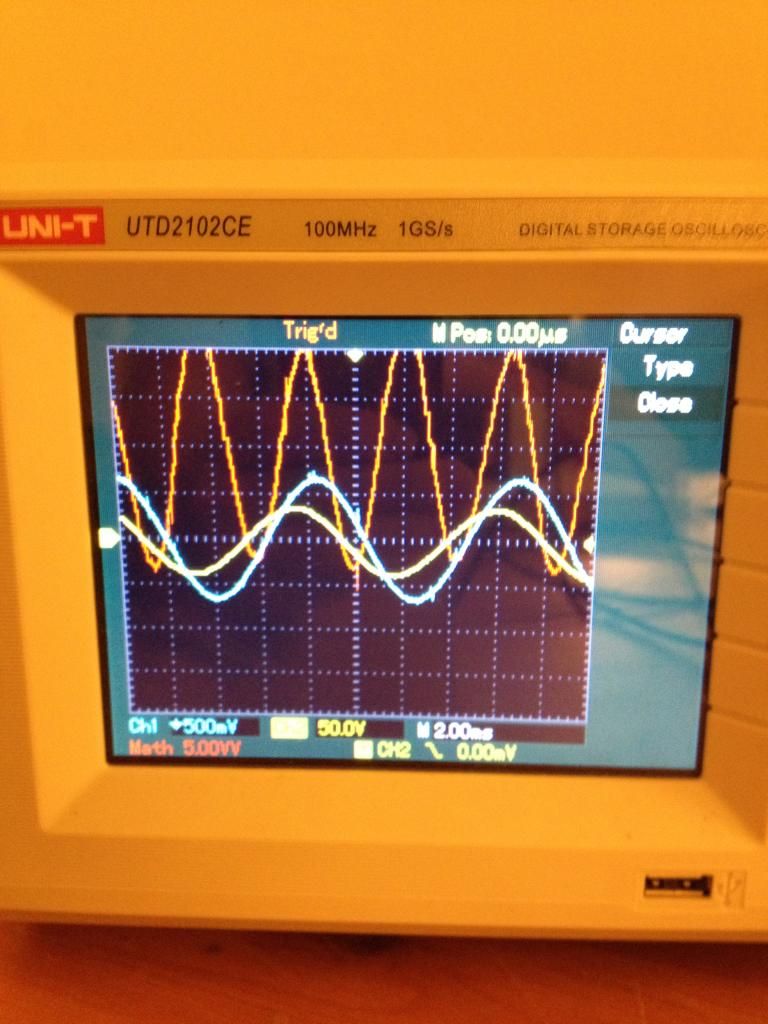
These wave forms are 2) from the resonant tank driving the primary of the
ferrite transformer and 1) is from the wire wound inductive resistor
load. Blue traces are the voltage sensed across a 0.1 Ohm resistor to determine
the current.
..Attached FilesLast edited by Farmhand; 09-27-2014, 01:08 PM.Leave a comment:
-
-
Exciting Results
That is so good. You are in lead position here.Originally posted by Web000x View Post
Way ahead of me because I can't work my 1 mhz 2 channel scope yet.
Keep up the good experiments showing mostly never beofre seen results and don't listen to people who have no working setup either.
If people think it is totally explainable, how can the explain away something they can't produce? The others just don't want to prove this stuff right.
You have done it. Top Dog so far in my book.
MikeLeave a comment:
-
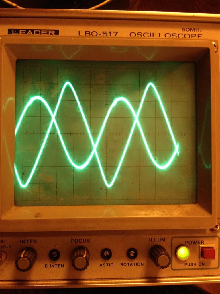
This is a scope shot using an analog scope. The amplitudes are different than from the previous digital scope shot so you can observe the voltage as having a spike on the crests. Still you see a a 90+ degrees cosine angle while there was light emitting from my lamp.Last edited by Web000x; 09-27-2014, 06:34 AM.Leave a comment:
-
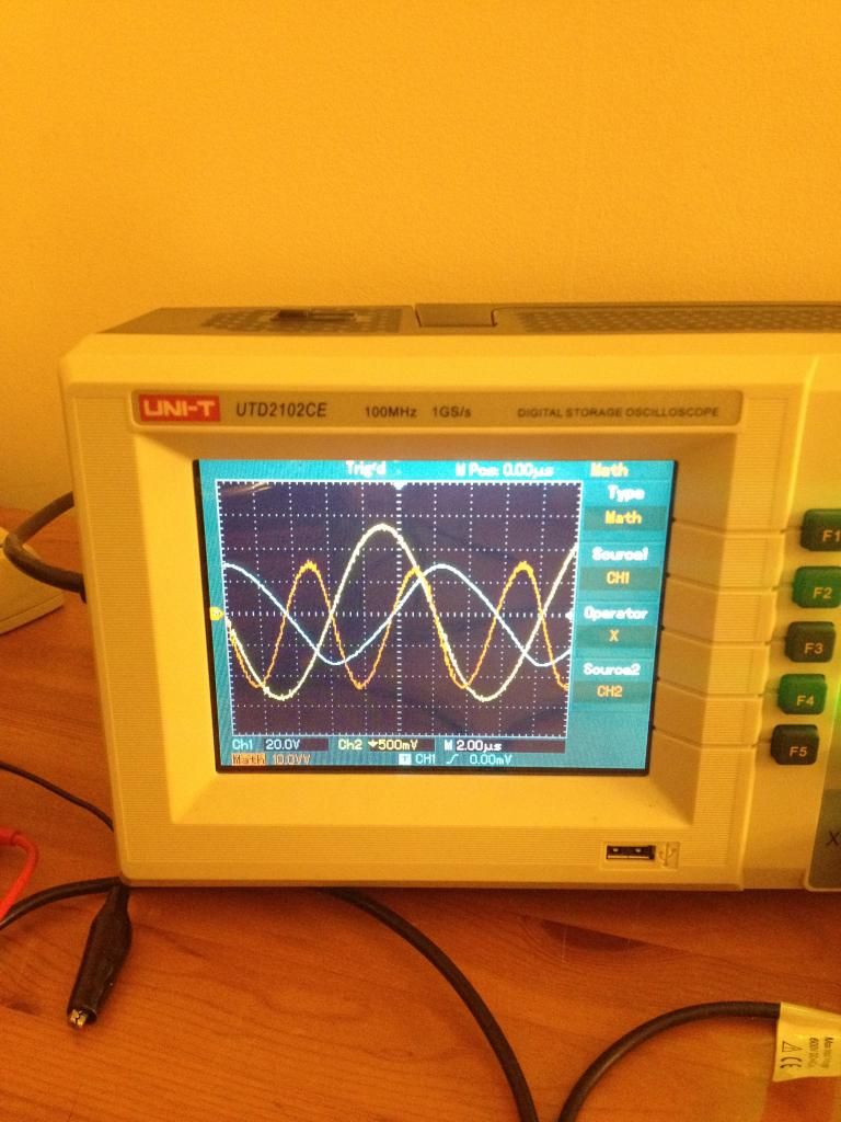
This is a close up of my wave. The circuit has capacitance in the secondaries so the current is leading the voltage. The power wave can be distinguished as redish and 2x the fundamental frequency. NOTE the area under the power wave which is directly representative of energy exchange.Last edited by Web000x; 09-27-2014, 06:17 AM.Leave a comment:
-
Apparently it will be one pic at a time..
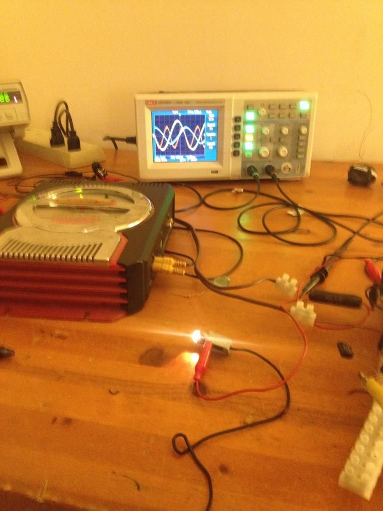
This shows my lamp dissipating energy and the scope in the background.Leave a comment:
-
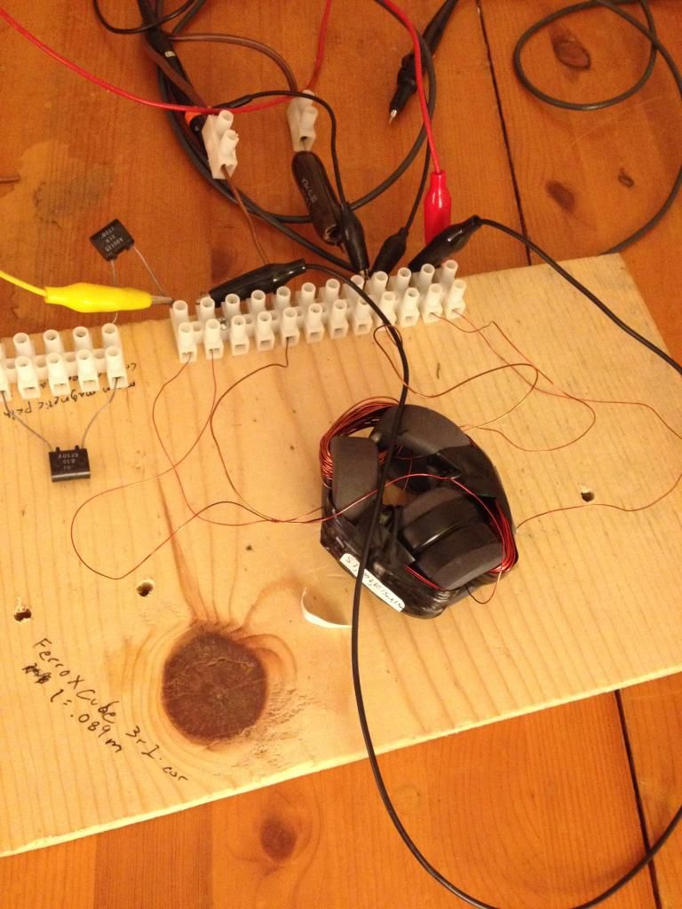
I encourage everybody to follow the Thane Heins concept. I've began to see interesting results. I've only been seeing these for two days and still trying to hunt out any flukes, but I'm starting to consistently be able to produce a negative power factor while powering a small lamp. The phase angle has been displaced well above 90 degrees. I measured at a dead short a phase angle of 106 degrees and with the lamp, 105 degrees, according to my scope which I plan on double and triple checking elsewhere. I'll post some pics when I can figure out why my computer won't let me access photobucket.
Cores - FerroXCube - 3r1
Secondaries - 2x 100t 26AWG
Primary - 38t 23AWG
DaveLeave a comment:
Leave a comment: