This forum is preserved as a permanent archive. The community continues at eMedia Press.

Announcement

Collapse
No announcement yet.

Stingo Solid State Battery Charger

Collapse
X
 
  • Filter
  • Time
  • Show
Clear All
new posts

  • 7imix
    replied
    Originally posted by Jiffycoil View Post
    I was powering my single wire pancake coil with the Stingo the other night and I was placing Neo magnets in the center tube to see the effects. One effect with a large 1/2 inch sphere is that the coil holds the magnet at dead center of the coil in the tube. It will lift it off the table and it hovers inside the tube. Secondly while playing with a smaller sphere I noticed it would spin for a moment once in the center of the tube. So I placed it on top a small plastic tube inside the tube the pancake coil is wound on and the magnet spun up and ran like a single magnet Bedini motor. I was amazed by this. Has anyone else had this experience. I filmed the small magnet spinning if anyone would like to see it.
    Very awesome. I am going to try this. Yes, please upload the video, I'd love to see it.

    A magnetic vortex...

    Leave a comment:


  • Jiffycoil
    replied
    Stingo Neo Spinner

    I was powering my single wire pancake coil with the Stingo the other night and I was placing Neo magnets in the center tube to see the effects. One effect with a large 1/2 inch sphere is that the coil holds the magnet at dead center of the coil in the tube. It will lift it off the table and it hovers inside the tube. Secondly while playing with a smaller sphere I noticed it would spin for a moment once in the center of the tube. So I placed it on top a small plastic tube inside the tube the pancake coil is wound on and the magnet spun up and ran like a single magnet Bedini motor. I was amazed by this. Has anyone else had this experience. I filmed the small magnet spinning if anyone would like to see it.

    Leave a comment:


  • cikljamas
    replied
    Originally posted by sucahyo View Post
    I only certain if someone elese can replicate it .
    I have to go back to your previous posts to see what you have done
    and try to repeat it, than we ll see...

    Originally posted by sucahyo View Post
    It is one of the idea of Tesla Switch, charge in paralel use in series as source.
    I wont try to connect it in series before you tell me how great risk is for
    stingo to use 24 V as source...So, if i understood you well, i should use
    as source two primary batt. connected in series, and charge two other batt.
    connected in parallel ?...I will try just to see what will happen to charge
    two charging batt. in parallel, but only with one primary batt...If you think
    that 24 V will not jeopardize transistors of stingo than i will try two primarys
    in series too...I lost several tip 3055 and tip 2955 , and they are 1.5 $ each
    here, so...
    Originally posted by sucahyo View Post

    Never. I think you should use bigger wire. I think self oscillation need inductance, but since you use bigger toroid you can use bigger wire to obtain the same amount of winding. I will look forward for your result .
    .
    Well, i made today just one stingo (not two, as i thought i was going to make yesterday), it took me 3 hours for winding toroid, and 1 hour for
    soldering stingo...
    And i tried this new stingo with that big toroid, and i am not content
    with results, just about 30 % efficiency, maybe wrong wire or wrong
    number of wounds, or both, who knows.

    Originally posted by sucahyo View Post

    Thanks . I agree that winding the toroid is painfull .... so I use it to calm my heart after it is done (as radiant sleeping aid).
    I go step by step, so i havent finished my stingo efforts towards as good
    efficiency as it is possible, but i think i am not going to improve it much
    more (though i have to be content with this results too !!!)...But after i
    conclude that it is it, i am going to try other stingo variants...First of all
    it is going to be that radiant sleeping aid of course !

    Cheers!

    Leave a comment:


  • sucahyo
    replied
    Originally posted by cikljamas View Post
    Why not ?...What is the advantage of lead acid b. ?
    SLA use gel that won't absorb water if it dry. Lead acid use water which may also do magical thing I guess.

    Originally posted by cikljamas View Post
    Could it be for real ? I mean, how come that meter is just fooled in the one moment and in the other moment is ok, dont sound convincing, dont you think so ?
    I only certain if someone elese can replicate it .


    Originally posted by cikljamas View Post
    This idea with paralleling load battery is really interesting one...Could you explain this part with series the source ?
    It is one of the idea of Tesla Switch, charge in paralel use in series as source.

    For stingo paralleling load give greater benefit because stingo will be more efficient with lower impedance load. The problem is too low can kill oscillation.


    Originally posted by cikljamas View Post
    Have you ever tried your stingos with big toroid, and if you did what was the result ?
    Never. I think you should use bigger wire. I think self oscillation need inductance, but since you use bigger toroid you can use bigger wire to obtain the same amount of winding. I will look forward for your result .

    With bigger wire and bigger toroid, I thing the output will be strong enough to kill transistor if not carefull....

    Originally posted by cikljamas View Post
    You see, i am very busy making new stingos...I told you, i am in love with them, more and more...
    But i must complain a little bit too : I got pain in my heart, pardon, EARS !!!
    YouTube - The Osborne Brothers - Pain in My Heart
    Thanks . I agree that winding the toroid is painfull .... so I use it to calm my heart after it is done (as radiant sleeping aid).

    Leave a comment:


  • cikljamas
    replied
    Originally posted by sucahyo View Post

    I think lead acid is the key to get your result. We may not have same result with SLA.
    Why not ?...What is the advantage of lead acid b. ?

    Originally posted by sucahyo View Post
    Thanks for the transistor tips everyone .
    You are welcome !

    Originally posted by sucahyo View Post
    However, I think we should prepare too that it give too unbelieveable result, this is example of what look like a COP = 10 result, using the circuit above. But I doubt it really COP>1, maybe the meter is just fooled.
    Could it be for real ? I mean, how come that meter is just fooled in the
    one moment and in the other moment is ok, dont sound convincing, dont
    you think so ?


    Originally posted by sucahyo View Post
    No, stingo is just a derrivative of Bedini circuit . Begini get more awesome result .
    Than, pupil surpassed his master !

    Originally posted by sucahyo View Post

    We get lower amp out if we charge 12V battery. What is the difference?
    Impedance. 12V is 6 cell of 2V. In order to get lower impedance from 12V battery, we should parallel them. By paralleling load battery, we get lower impedance and hopefully get higher amp output too.

    The usual trick to parallel the load and series the source can also work too.
    .
    Yeah, you are damn right ! That is why i got cop = 1 when i charge
    cell phone battery with stingo, and when i charge other 12 V battery
    than it is "only" 0,6...This idea with paralleling load battery is really
    interesting one...Could you explain this part with series the source ?

    And, you know what ? This remind me to Ossie Callahans REAC (radiant
    energy accumulator - converter)...I already work on preparations to practise
    his radiant energy battery charging system, he claims OU with it,
    but we have to see, untill i see with my own eyes, i do not believe it, but
    i must try it, that is for sure...

    I spent last day looking for broken power supply to pull out more toroids,
    and i did it...Tomorrow i am going to make two more stingo...
    Yesterday i disassembled one big toroid ( i just left primary )...
    I am curious to try new stingos with this big one...
    Have you ever tried your stingos with big toroid, and if you did what
    was the result ?
    You see, i am very busy making new stingos...I told you, i am in love
    with them, more and more...
    But i must complain a little bit too : I got pain in my heart, pardon, EARS !!!
    YouTube - The Osborne Brothers - Pain in My Heart

    Cheers !

    Leave a comment:


  • sucahyo
    replied
    I do some modification to the FWBR combiner. But, I don't know if this will improve anything. It is just an accumulation of what I thought to be the best configuration. The reason:
    - to combine radiant circuit output
    - to also capture coil back spike
    - prevent the source from powering the load directly, only a brief moment after the spike (capacitor provide the bouncing)
    - diode from source negative allow possibility to charge the source


    I use only two stingo for my charger:


    The output so far is about the same as previous circuit. Since the capacitor only block the current from battery, the stingo see the load as higher impedance load and thus draw less current.

    Leave a comment:


  • sucahyo
    replied
    Originally posted by 7imix View Post
    Which bedini circuit? I haven't built any bedini circuits, I would love some pointers to which circuits are good to try building.
    The beginning, Bedini monopole or SSG.

    Leave a comment:


  • 7imix
    replied
    Originally posted by sucahyo View Post

    No, stingo is just a derrivative of Bedini circuit . Begini get more awesome result .
    Which bedini circuit? I haven't built any bedini circuits, I would love some pointers to which circuits are good to try building.

    Leave a comment:


  • sucahyo
    replied
    Originally posted by Farmhand View Post
    Hi all, My Stingo finally works , Here I have a couple of picture's.

    Stingo Sulute.


    Stingo Waving to Sucahyo


    Stingo is charging a battery for me first, I used an old quadfiler coil I had only using one winding through a bridge to charge battery, he works very good. 250 Ma min draw and more than 600Ma max, haven't warmed him up yet.

    Unfortunately I have to go on a short work trip, maybe a couple of days, not sure when I will go yet. I'll try to keep up by wireless, but it may not work very well.

    Regards
    Congratulation . Thanks for the wave shot .

    That picture make me wonder if we will get that kind of wave on whatever frequency when charging? Because obtaining that kind of wave only appear at spesific frequency in SSG? Anyone can confirm?


    Good luck .

    Leave a comment:


  • Farmhand
    replied
    Hi all, My Stingo finally works , Here I have a couple of picture's.

    Stingo Sulute.
    http://koyg9g.bay.livefilestore.com/...ute.png?psid=1
    Stingo Waving to Sucahyo
    http://koyg9g.bay.livefilestore.com/...ing.png?psid=1
    Stingo is charging a battery for me first, I used an old quadfiler coil I had only using one winding through a bridge to charge battery, he works very good. 250 Ma min draw and more than 600Ma max, haven't warmed him up yet.

    Unfortunately I have to go on a short work trip, maybe a couple of days, not sure when I will go yet. I'll try to keep up by wireless, but it may not work very well.

    Regards

    I forgot to say thank you to Godfrey for posting the basic Stingo drawing for me, it helped a lot.
    Last edited by Farmhand; 11-18-2010, 03:55 AM. Reason: Fixed links

    Leave a comment:


  • sucahyo
    replied
    Thanks for the transistor tips everyone .


    Originally posted by skaght View Post
    I'm running my stingo/slayer (I've dubbed it the Sting-slay) combination circuit and charging a lead acid battery at ~500 kHz. It has an h shaped output on my scope, and the transistors are both cold--I can't detect any heat from either NPN or PNP.
    That a very high frequency . thanks for the h shape info .

    Originally posted by cikljamas View Post
    Well, what i tried is two stingos and three coils (i wound third one) and i think this is absolutely ok for the purpose that i need this, and not just that, i combined it with bedini ssg, and what we got, let see in my new video...
    YouTube - stingo bedini 1
    I shot this video two hours ago, and there is still no discharging of my
    primary battery...weird...
    Very interesting result . Primary that driven stingo and secondary that driven bedini is self charging too . And you get the primary increase voltage instead of getting discharged. That is awesome .

    I think lead acid is the key to get your result. We may not have same result with SLA.

    Originally posted by Godfrey View Post
    Inspired by JiffyCoil’s and Skaght’s 1.5V results, I decided to run a 1.5V battery test with the toroid and was pleasantly surprised to see it oscillate well and light a neon bulb:
    Nice . I want to be able to do it too....

    Originally posted by Godfrey View Post
    Here is a scope shot sampled at the output, showing very sharp, 90+V spikes. The duty cycle is about 1.2 %:

    ...

    Take a look at that output scope shot I just posted. It illustrates exactly what 7imix is talking about. I hooked the positive lead of the scope to the radiant positive output and the negative lead to the radiant negative (battery positive, due to reverse spike).

    The top of the spike goes off my 10V scale, but you can see that it is almost all positive, except for a little joggle at the end, making it ideal to use as an HV input impulse, as 7imix has so well illustrated.
    Thanks. I found that very interesting . NO backspike should be usefull for spark experiment ....


    Originally posted by cikljamas View Post
    Well, i succeeded to measure mAmps before my last meter was busted :
    input : 23 mA
    output : 20 mA
    Now if we count 80 V output comparing 12 V input it should be OU
    because 20*80 = 1600 and 23*12 = 276, so 1600 > 276, but somehow
    it does not work like that...P = U x I, but...2 x 2 is not always 4...
    I measure it like this:


    COP = (output voltage * output current) / (input voltage * input current)


    However, I think we should prepare too that it give too unbelieveable result, this is example of what look like a COP = 10 result, using the circuit above. But I doubt it really COP>1, maybe the meter is just fooled.
    YouTube - stingo 3V charge 3V cop 10?

    The video show 3V charging 3V, where the input current is 420mA and the output is 4000ma if I touch the wire.

    Originally posted by cikljamas View Post
    I must give stingo the credit : with just two stingos and three coils i achieved 60 % of efficiency : input 320 mA---output 190 mA... It is now better then my bedini 4 coils which result is : input 380 mA, output 190 mA...Sucahyo is better in electronics than Bedini is !!!
    No, stingo is just a derrivative of Bedini circuit . Begini get more awesome result .


    Here is another trick to try to get COP>1 with stingo. This trick require circuit that reduce consumption with load, like stingo.

    The trick is to reduce load impedance.

    I think some of you already experience getting higher amp out than in. I notice that happen if I charge 3V battery with 12V source input. We get lower amp out if we charge 12V battery. What is the difference?

    Impedance. 12V is 6 cell of 2V. In order to get lower impedance from 12V battery, we should parallel them. By paralleling load battery, we get lower impedance and hopefully get higher amp output too.

    example, with rough number
    2 nicad impedance = 0.7 ohm
    6 lead acid impedance = 5.4 ohm

    How do we get 0.7 ohm impedance with 12V battery?
    6 / 0.7 = 7.7

    we need 8 battery to get nicad impedance.


    If we use 12V source, we use more 12V battery at load in parallel. The conventional measurement result would then get us COP>1 . Is it a valid COP>1 or not? who knows. I don't have many battery......


    The usual trick to parallel the load and series the source can also work too.


    To get more impressive result using above COP calculation, measure when the load battery is full .


    But for the real COP > 1, I think cikljamas has done it .
    Last edited by sucahyo; 11-15-2010, 02:21 AM.

    Leave a comment:


  • cikljamas
    replied
    I must give stingo the credit : with just two stingos and three coils
    i achieved 60 % of efficiency : input 320 mA---output 190 mA...
    It is now better then my bedini 4 coils which result is : input 380 mA,
    output 190 mA...Sucahyo is better in electronics than Bedini is !!!
    Did you know that ???
    Now, what is left to do is to be better then Waykykjy (if i good remember
    his nick)...Lets get ready to rumble !!!
    Let me see your hands...
    Sing with me : We shall overcome...
    I dont hear you...Louder, please !
    Sucahyo, do you believe it is possible ?
    What do you say about my calculations in my previous post ?
    What is the catch 22 in OU case ?
    Just to replicate someone elses already existed project or to always
    discover hot water from the beginning as one croatian byword says ?
    And if someone want to know, why we try to achieve OU , than we
    should answer as alpinists do when someone ask him why they climb
    difficult climbs : BECAUSE IT IS THERE (MOUNTAIN) or in our case OU!!!
    Dont you think so ? All alpinists want to climb Mt. Everest, isnt that
    the same with us who are in love with electronics ? So, how come we
    are not already there ? I can not bear that some guy in South Africa
    has such a beautiful project locked ih his drawer and we know that
    he has it but such a huge number of other people cant replicate it...
    It is for Ripleys believe it or not !!!

    Leave a comment:


  • cikljamas
    replied
    Well, i succeeded to measure mAmps before my last meter was busted :
    input : 23 mA
    output : 20 mA
    Now if we count 80 V output comparing 12 V input it should be OU
    because 20*80 = 1600 and 23*12 = 276, so 1600 > 276, but somehow
    it does not work like that...P = U x I, but...2 x 2 is not always 4...
    I need something like this :
    webcafe.hr - forwarduše / video
    to jump across that barrier, but maybe
    we should first have to know what is this barrier ???

    all the way up to "how you turn this off?"
    It is interesting story how it happened but i ll tell you that story some
    other time...In the meantime enjoy my clumsiness !

    Leave a comment:


  • Godfrey
    replied
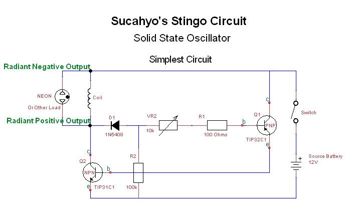
    Simplest Stingo Circuit

    Originally posted by Farmhand View Post
    ...Could you please point me to your most recent, and most basic Stingo please, I should build a basic one first I think.

    I might understand him better that way.
    Hi Farmhand, thanks for participating! Here is the basic Stingo circuit that got me going:


    - Godfrey
    Last edited by Godfrey; 11-14-2010, 01:03 PM.

    Leave a comment:


  • Godfrey
    replied
    Originally posted by 7imix View Post
    I did some experiments with my original stingo sparker and the pancake coil I just built.

    With the high voltage output hooked up to the coil primary and the spark gap, and one side of the fluorescent bulb hooked up to the center tap of the bifilar coil, the fluorescent lights. One wire transmission.

    The stingo produces the correct shape impulses without the spark gap, too, and in the second part of the video I show the fluorescent lighting without the gap sparking.

    YouTube - one-wire
    Originally posted by sucahyo View Post
    You mean stingo produce spike without a backspike ?
    Originally posted by 7imix View Post
    Yes. It produces a little backspike, but compared to the magnitude of the upspike it's almost nothing.

    Except since in the radiant recovery part of the circuit the leads are reversed, what I'm describing actually is the backspike... but from the reversed perspective it looks like an upspike...
    Take a look at that output scope shot I just posted. It illustrates exactly what 7imix is talking about. I hooked the positive lead of the scope to the radiant positive output and the negative lead to the radiant negative (battery positive, due to reverse spike).

    The top of the spike goes off my 10V scale, but you can see that it is almost all positive, except for a little joggle at the end, making it ideal to use as an HV input impulse, as 7imix has so well illustrated.
    Last edited by Godfrey; 11-14-2010, 11:05 AM.

    Leave a comment:

Working...
X