
irrelevant post coming.....
Why did you choose to call your circuit's "stingo"?
-
Thanks guys for the replies.
I persisted and tried the HDD motor.
What a buzz.
Runs as low as 3.0v and screams at 12v.
I will load up a you tube shortly.
I configured this as the charger as well , and though I am seeing the spikes
on the CRO, I could not get battery to charge any ?
Once again, thanks sucahyo and 7mix.
Regards, Penno
Sorry guys, it is charging. I was biting off more than I could chew. I was trying to charge a 12v.
On a 1.2 Ni-Mh, charges and rather quickly too.
ThanksLeave a comment:
-
I have found car ignition coils to be the easiest to oscillate. The bigger the coil, the lower the resonant frequency. Since most transformers are iron core this lowers the frequency even more.
Also, as I mentioned once in passing, sometimes disconnecting and reconnecting the circuit with the pot set in the right position will kick it into gear. The initial transient probably gives it the kick it needs to open the first transistor and start the oscillation. Try adjusting the pot a little and then opening and closing the circuit, and repeat.
Try different size batteries... try 6 volt and 12 volt.
Also, perhaps your circuit has a short or is connected improperly... Can you take pictures of your build and upload them so we can check for accuracy?
Thanks for trying stingo, it's fun :-)Leave a comment:
-
Hi guys,
I have spent the last couple of nights trying to get this simple circuit to osciliate.
I have tried countless coils, transformers from PC psu, pinball machine coils all to no avail
For my transistor pair, I am using TIP 31 and 32.
10k pot and 100 ohm.
I have also tried 7mix 100k to ground circuit.
Any tips, greatly appreciated.
Kind Regards, PennoLeave a comment:
-
Thanks 7imix .
.
If your coil is not oil filled, maybe you can fill it with oil.Originally posted by Godfrey View Post
Thanks for the info. I never know such different existOriginally posted by Godfrey View Post. All I know that other people complain headache when doing experiment with car coil. I guess different way of switching can make a difference.
Did you connect the common terminal to battery positive?
I think it depend on the coil resonant frequency. If the coil have iron core, it would prefer low frequency.Originally posted by Godfrey View Post
Yes.Originally posted by Godfrey View Post
No. To be sure I retry it again with complete circuit today. With car coil the neon bulb is brighter when the secondary is shorted. and I recall that with analog volt meter my air core transformer give the opposite result, less output voltage with shorted secondary. I think the core type can change result..Originally posted by Godfrey View Post
YouTube - Stingo shorted secondary experiment
That is the origin of the name stingoOriginally posted by Godfrey View Post. I sting my hand and found this weird circuit....
I will look forward for your result.
Last edited by sucahyo; 10-21-2010, 02:04 AM.Leave a comment:
-
Here's the post I built my first sparker from.
http://www.energeticforum.com/renewa...html#post99691
I've built a few of these, sometimes I use a 1000 ohm resistor and sometimes I use a 100 ohm.
Thanks for the cool info, godfrey. I've got some fun stuff to share, I'll post in the stepper motor thread.Leave a comment:
-
Originally posted by SucahyoOriginally posted by SucahyoOriginally posted by SucahyoDo you mean the simple circuit failed when you shorted the secondary too?Originally posted by Sucahyo
Originally posted by SucahyoLeave a comment:
-
greatOriginally posted by Godfrey View Post . I get brighter neon with my transformer than my car coil.
Mine reach 1000V on analog, about 800 on digital multimeter. Maybe you need higher.Originally posted by Godfrey View Post
Do you test it with full circuit or the simple one? Now that you mention it, I seem to test it with the simple version. The one with neon load at primary use my hand as resistor.Originally posted by Godfrey View PostLeave a comment:
-
I've been putting together a new higher voltage Stingo using a TIP2955/TIP3055 pair. I got it working with a toroid coil at 6V and 12V and one of my ignition coils at 12V. They both light a neon bulb across the output and I got the ignition coil secondary dimly lighting a florescent bulb. I'll be posting pics of my setup, scope shots and current measurements. I'm very hesitant to subject my little scope with the 1x probe to the output. I'm ordering a 10x probe that will be good for up to 300V, and gathering ideas on how to make my own HV probe.
Originally posted by SucahyoGee guys, I'm really scratching my head over this one. Not only my little 3V transformer, but the toroid coil is acting this way. I've got a switch which I've flicked off and on several times to try and get it working, with a shorted secondary. I can even start and stop the oscillator by disconnecting and connecting the secondary short, while the circuit is on!Originally posted by 7imix
Running a load on the secondary of the small transformer and the car coil worked. I haven't tried shorting the secondary on the car ignition coil or running a load on the secondary of the toroid coil yet. Will investigate further.
- GodfreyLeave a comment:
-
Yes.Originally posted by 7imix View Post
BTW, I get blackout again last night and try both parallel and series. It seems both have similar brightness. So I goes power out is the same on any configuration. High voltage low current while in series has brightness equal to low voltage high current in parallel. I don't measure input power though.Leave a comment:
-
Very interesting result Godfrey .
But add at least 100 ohm between the PNP and potentiometer to prevent you from burning up the PNP.
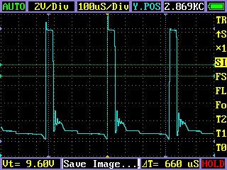
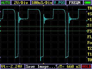
It is interesting that you get two sweet spot. It also show different wave form. one with bouncing, other don't.
You don't get oscillation with secondary being shorted? try reconnect the power. Don't short it while running.
I use TIP2955, TIP32C and 2SB507. I prefer the cheapest TIP32C though. I don't think I can notice the difference.Leave a comment:
-
Cool, dude, thanks for the test and scope shots.
I have been working on something else for a bit, but hopefully I'll get back to testing stingo soon.Leave a comment:
-
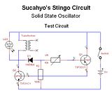
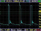
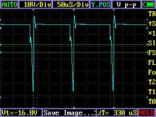
Now the 3V test bed gets interesting because the output does not overwhelm the scope or 1x probes :
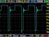
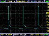
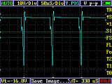
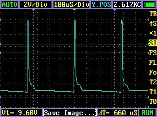
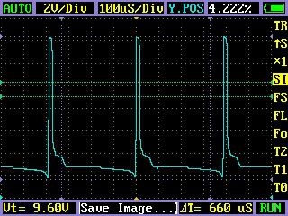
As I turn the knob more to the right, duty cycle %, decreases. The frequency declines in the middle. Then the frequency starts to rise again, and I hit a new sweet spot around the last third of the knob where the frequency peaks again at around 2.6kHz :
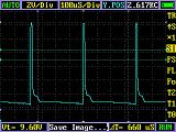
The duty cycle drops to 4.2% :
 DSO201 Nano Oscilloscope Forum
- Godfrey
post note: One important measurement I left out was output current...only way to really tell what the total power output of the radiant spikes were.Last edited by Godfrey; 10-13-2010, 04:28 AM.Leave a comment:


Leave a comment: