This forum is preserved as a permanent archive. The community continues at eMedia Press.

Announcement

Collapse
No announcement yet.

Stingo Solid State Battery Charger

Collapse
X
 
  • Filter
  • Time
  • Show
Clear All
new posts

  • sucahyo
    replied
    Originally posted by Godfrey View Post
    Why have the single toroid coil paired with a car ignition coil? Is the single coil stingo feeding the one with the car coil in a staged configuration?
    That just an actuall implementation, something that I already have. It is not that important. But what you mention also happen, the circuit have effect on each other, that the other coil may still works even if you pull some of its component ....

    Just like what in front of me now, I add relay based oscillator to the FWBR merger, the relay sing too .


    Originally posted by Godfrey
    Although I haven't experimented with them enough to measure their characteristics, I think that a bifilar coil's type of capacitance may help preserve/pass on radiant energy.
    Well, just try it. I found that sometimes implementation defies theory. Stingo teach me that . So I am not that surprise if I am wrong now . But please compare bifilar and single filar having same impedance, core and wound.

    Leave a comment:


  • Godfrey
    replied
    Thanks for the video and scope shots, 7imix. Very interesting!

    Originally posted by 7imix
    I replicated a low voltage version of it and took some scope shots
    What's different about your circuit. 3V? What coil?

    Originally posted by Sucahyo
    Capacitor and battery will partially change the radiant to normal electricity. If you charge it directly with radiant output the battery will stays cool. If you use capacitor dumping mechanism the battery will get hot.
    Thanks, that's really useful data.

    Originally posted by Sucahyo
    toroid wound coil like the one I post before. That just my actual circuit. The coil can be anything and you still get better efficiency with two.
    Why have the single toroid coil paired with a car ignition coil? Is the single coil stingo feeding the one with the car coil in a staged configuration?

    Originally posted by Sucahyo
    From what I recall Peter Lindemann once mention that bifilar coil will make the coil collapse current to flow to each other coil. He said that for radiant recovery, bifilar may not be optimal.
    Although I haven't experimented with them enough to measure their characteristics, I think that a bifilar coil's type of capacitance may help preserve/pass on radiant energy.

    - Godfrey

    Leave a comment:


  • 7imix
    replied
    In the recent thread about don smith, there was a link to a long document that had a 555 timer circuit near the end of it. The circuit is for driving a spark gap to resonate a tesla coil. I replicated a low voltage version of it and took some scope shots.

    YouTube - Don smith trigger circuit

    Sorry for the video being sideways.

    The stingo impulses have nicer slopes, but this is meant as input to a spark gap which produces the nice steep slope.

    Leave a comment:


  • sucahyo
    replied
    Originally posted by Godfrey View Post
    Ok, you asked I'm working on a CMOS 555 based frequency/pulse-width dynamically controlled power stepper. The kind of stepped power one might drive a motor with or control the heater on a soldering iron.
    I see. Good luck .

    Be carefull when playing with spark, I kill two 555 and 5 computer fan when I get spark at primary. Watch out the heat too, it can melt transistor core.
    Last edited by sucahyo; 10-08-2010, 02:18 AM.

    Leave a comment:


  • Godfrey
    replied
    555 Signal Generator/Power Stepper

    I see. What you want to use 555 for?
    Ok, you asked I'm working on a CMOS 555 based frequency/pulse-width dynamically controlled power stepper. The kind of stepped power one might drive a motor with or control the heater on a soldering iron.

    Application-wise, Producing maximum sensory feedback about radiant production/recovery - wadititisanwaditshudbe It's exclusively for testing and measuring different coil designs. Spark-gaps, as previously mentioned, too, as well as EVGray tube type devices. So got to say it's more than a signal generator because I intend to pulse various levels of power into the target device. I'll also be aiming to scale down and minimize any HV heavy going on, being primarily concerned with constructing a safe, portable, and informative testing environment.

    I'll always be driving a power switch with the 555 signal. The Stingo setup may just be the sharpest way to do the switching...capiche?

    - Godfrey
    Last edited by Godfrey; 10-07-2010, 01:56 PM.

    Leave a comment:


  • sucahyo
    replied
    Originally posted by Godfrey View Post
    ??? – I’m not understanding – Do you mean that the sharpest (shortest) pulse produces the best radiant energy for health purposes? Can you elaborate further?
    Yes. I believe that the sharpest pulse (may not be shortest) produce healthier radiation. I feel it from my past experiment prior PNP+NPN combination.

    Tesla used very fast mechanical current disrupter. With solid state I am thinking that we have to use the sharpest drive signal. There is other reference which I forgot where that mention that stinging sensation reduce with higher switching, changing to warmth, and then cool.

    Coincidentally, the most abrupt switching, the most sharp signal, also produce better efficiency.

    Originally posted by Godfrey View Post
    What’s important is it showed me how to feed the Stingo transistors with the 555 signal.

    I have my own ideas about how to do the 555 timer part. I’ll be replacing the timing resistors with potentiometers, and configuring it differently to control frequency and pulse width, independently. Your configuration with the diode gives you independent control of Mark and Space, which do add up to a frequency, but not in a single dial way. I would also decouple the power to the timer more by adding a big capacitor in parallel to the power rails and a resistor in series with pin 8 to help it deal with the spikes.
    I see. What you want to use 555 for?

    BTW, can you test charging efficiency once you done building 555 one? From what I recall, stingo is twice more efficient than my 555 version. But I still use a power hungry 555 at that time.

    Originally posted by Godfrey View Post
    Using a CMOS 555 reduces these issues considerably. It consumes much lower power, and its timing is less sensitive to voltage changes. I’ve been using TLC555CP. They are delicate, however, and in my experience, the timing varies (usually faster) from non CMOS ones like the NE555, even though the formulas look the same on the spec sheets. This is one of the reasons I desired accurate frequency measurement and picked up the Nano.
    I see. thanks for the info. My lowest current consumption with 555 is under 10mA.


    Originally posted by Godfrey View Post
    Thanks for the tech observations, but the question I’m really pondering is: How different will the stored radiant energy be from that being given off fresh by an oscillating circuit? Does it really come out the same if stored and pulsed out later? Or are the qualities/effects of radiant energy coming right out of a generating circuit as spiked pulses unique?
    Capacitor and battery will partially change the radiant to normal electricity. If you charge it directly with radiant output the battery will stays cool. If you use capacitor dumping mechanism the battery will get hot.

    I find that even capacitor in parallel with charged battery will make the charging hotter.

    Originally posted by Godfrey View Post
    Sucahyo, I forgot to ask you what that single coil is in your dual Stingo configuration? I assume the other one is a car coil.
    toroid wound coil like the one I post before. That just my actual circuit. The coil can be anything and you still get better efficiency with two.


    Originally posted by Godfrey View Post
    Relating to your investigations, Tesla seems to have discovered that the bifilar coil filters the reverse electromotive force while passing on the radiant energetic reaction to the spike.
    From what I recall Peter Lindemann once mention that bifilar coil will make the coil collapse current to flow to each other coil. He said that for radiant recovery, bifilar may not be optimal.
    Last edited by sucahyo; 10-06-2010, 09:44 AM.

    Leave a comment:


  • Godfrey
    replied
    Originally posted by Sucahyo
    But I spesifically after the radiant produced by the steepest signal for health reason
    Originally posted by Sucahyo
    You have seen this circuit of mine?
    Originally posted by Sucahyo
    this circuit bellow have many wrong part.
    Originally posted by Sucahyo
    Some have great success with capacitor. Try with big capacity and use it to charge battery with relay or other mechanical switch.
    Originally posted by 7imix
    yep. Parallel is better.
    Good info! Thanks.

    Originally posted by 7imix
    That is what I am interested in seeing. The bemf is not as interesting to me as driving the sharp sloped spikes into a tesla transformer with a termination. (probably a dead light bulb) Since the bifilar coil reduces back emf through self induction (I am assuming...) this setup should produce maximum dielectric induction, or displacement current. That is what I am most interested in researching.

    Leave a comment:


  • sucahyo
    replied
    Originally posted by 7imix View Post
    yep. Parallel is better. That's what I ran in my experiment, I should have made it more clear.
    I see. Thanks .

    Leave a comment:


  • 7imix
    replied
    Originally posted by sucahyo View Post
    Actually, I have to try it sooner then expected. I have blackout last night and my emergency light run out of battery. Fortunately my radiant sleeping aid available and I use it to light 6 LED in series at about two candle light.

    Now I wonder if parallel is better, because stingo reduce consumption with more load, and parallel should force it...
    yep. Parallel is better. That's what I ran in my experiment, I should have made it more clear.

    Leave a comment:


  • sucahyo
    replied
    Originally posted by Godfrey View Post
    A very practical application to explore, glad 7imix is looking into it – great LED vids, 7imix!
    Actually, I have to try it sooner then expected. I have blackout last night and my emergency light run out of battery. Fortunately my radiant sleeping aid available and I use it to light 6 LED in series at about two candle light.

    Now I wonder if parallel is better, because stingo reduce consumption with more load, and parallel should force it...


    Originally posted by Godfrey View Post
    Originally posted by Sucahyo
    50V is measured output from 3V source.
    Wow! What kind of coil got you these results?
    1A 24V transformer without core. Kinda cheating though, the battery seems to be conditioned by my radiant charger and seems to exceed normal.


    Originally posted by Godfrey View Post
    However, I’m inclined to think that a specific frequency and pulse width changes the nature of the radiant energy being output. And so intend to develop a circuit that provides such precise control for experimentation. I would think that watching a spark as the pulses change would reveal some very interesting things.
    Yes, I agree to that. But I spesifically after the radiant produced by the steepest signal for health reason. I look for a way to drive the transistor with spike. I think stingo use radiant spike as trigger.

    During this time, Tesla found shorter impulse lengths where the heating effect disappeared altogether, rendering the radiance absolutely harmless. These impulse trains were so very high that the deepest nerves of one's body could not sense the permeating radiant energy field. Now he could
    pursue his vision of broadcast energy systems without fear of rendering to humanity a technological curse, rather than a true blessing.

    You have seen this circuit of mine? this circuit bellow have many wrong part.


    If you want to compare, try with and without duty-cycle-trick-diode. I forget which one I use. To reduce 555 consumption use more than 10K ohm duty-cycle-resistor. And to compensate for lowered frequency, use pico Farad capacitor, or don't use it at all. 100ohm for PNP base is too low, I use 10K on my charger. You might also try other circuit variation but keep the PNP+NPN combination.

    The 555 can not be called precise because frequency wander with input voltage. If you use battery, when your circuit draw more power the voltage change, and in turn will change circuit frequency.


    Originally posted by Godfrey View Post
    Here’s another thing I wonder about – How does storing the radiant energy in a battery or capacitor change it?
    Some have great success with capacitor. Try with big capacity and use it to charge battery with relay or other mechanical switch.


    1MHz scope still good enough for our experiment .

    Leave a comment:


  • Godfrey
    replied
    Originally posted by 7imix
    Here's my 4th stingo build.
    Awsome! Thanks, 7imix.

    Originally posted by Sucahyo
    Brushless motor can use stingo too, Godfrey refer to my last post on stingo motor thread. I just post my recent experiment result that show stingo outperform standard bedini fan.
    Thanks Sucahyo. Very interesting!

    Originally posted by Sucahyo
    I still don't explore stingo use for LED lighting.
    Originally posted by Sucahyo
    50V is measured output from 3V source.
    Wow! What kind of coil got you these results?

    Originally posted by Sucahyo
    No, each stingo use one coil.
    Originally posted by Sucahyo
    I don't need that. I currently have no use of "precise, dynamic control of frequency and pulse width". For charger stingo is more efficient. For spark maker stingo is more reliable. I don't have a scope so I won't be doing experiment on sensitive measurement.
    Originally posted by 7imix
    Stingo provides very precise, dynamic control of frequency. Controlling pulse width doesn't matter -- from my Tesla research, it's my opinion it is always the case that the narrowest pulse width possible will be the most beneficial. Stingo simply provides the narrowest pulse width that it can, which is better than any other circuit I have seen out there so far.
    Originally posted by 7imix
    I have firmware version 2.02. I haven't tried actually saving any waveforms yet, I'll try it and let you know if it worked.

    What clone do you have?
    Lordblacksuca

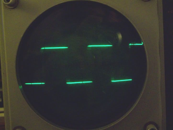
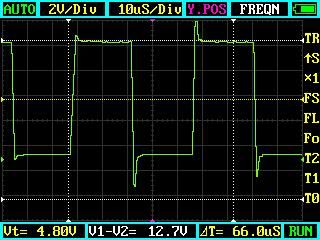
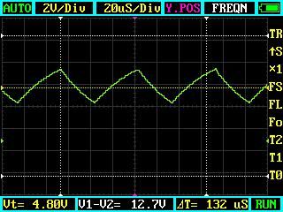
    Here are square wave pulses generated by a 555 timer circuit:


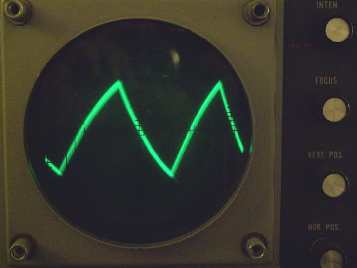
    Here is the capacitor charging cycle from the same circuit:


    Last edited by Godfrey; 10-06-2010, 05:30 AM.

    Leave a comment:


  • sucahyo
    replied
    Originally posted by 7imix View Post
    Sure, but the bedini fan has been modified, right? It's not connected to the original board which takes DC and produces pulses. Having the stingo pulse the input to the PCB which is supposed to produce pulses isn't going to work, is what I meant. The stingo needs to pulse a coil, which it is doing when it is hooked up to a bedini fan. Am I right?
    Modified means we split the wire. from 3 terminal (1 common) to become 4 terminal. The controller is unused. Standard JT way require us to reverse half of the winding.

    In stingo, the first half pulse the PNP, and the NPN drive the second half.


    Notice that I have to switch the leg when changing from standard to stingo. You may not need to add another terminal.


    Originally posted by 7imix View Post
    Godfrey inspired me to experiment with lower voltages, LEDs, and smaller transformers. I get similar results as when I did experiments with a joule thief, but I think this is even more efficient because the impulses are much shorter.

    YouTube - Stingo high frequency oscillations with small coil

    YouTube - Stingo LEDs
    Thanks for the video .


    Originally posted by 7imix View Post
    It's the equivalent of 2955/3055. I ran it today with 5v. I'll try with 1.5V.
    Thanks.


    Originally posted by 7imix View Post
    Stingo simply provides the narrowest pulse width that it can, which is better than any other circuit I have seen out there so far.
    I have been suspecting that but never sure. Thanks for the info .

    Leave a comment:


  • 7imix
    replied
    Originally posted by Godfrey View Post
    Show me a Stingo circuit that provides precise, dynamic control of frequency and pulse width and I'll agree with you.
    Stingo provides very precise, dynamic control of frequency. Controlling pulse width doesn't matter -- from my Tesla research, it's my opinion it is always the case that the narrowest pulse width possible will be the most beneficial. Stingo simply provides the narrowest pulse width that it can, which is better than any other circuit I have seen out there so far.

    If you can suggest a circuit that gives narrower pulses than the stingo, I'd like to replicate it. Thanks

    Leave a comment:


  • 7imix
    replied
    Originally posted by sucahyo View Post
    Brushless motor can use stingo too, Godfrey refer to my last post on stingo motor thread. I just post my recent experiment result that show stingo outperform standard bedini fan.
    Sure, but the bedini fan has been modified, right? It's not connected to the original board which takes DC and produces pulses. Having the stingo pulse the input to the PCB which is supposed to produce pulses isn't going to work, is what I meant. The stingo needs to pulse a coil, which it is doing when it is hooked up to a bedini fan. Am I right?

    I haven't built a bedini fan yet, I am going to do that next so I can replicate your latest youtube video.

    Originally posted by sucahyo View Post
    I still don't explore stingo use for LED lighting.
    Godfrey inspired me to experiment with lower voltages, LEDs, and smaller transformers. I get similar results as when I did experiments with a joule thief, but I think this is even more efficient because the impulses are much shorter.

    YouTube - Stingo high frequency oscillations with small coil

    YouTube - Stingo LEDs

    Originally posted by sucahyo View Post
    Cool . What is the spec of that transistor? Would it run on 1.5V battery?
    It's the equivalent of 2955/3055. I ran it today with 5v. I'll try with 1.5V.

    Leave a comment:


  • sucahyo
    replied
    Originally posted by 7imix View Post
    Yeah you need to use brushed motors. Computer fans have a little board that actually generates ac to drive the motor. Try a cheap toy, like maybe some rc slot cars or something.
    Brushless motor can use stingo too, Godfrey refer to my last post on stingo motor thread. I just post my recent experiment result that show stingo outperform standard bedini fan.

    Originally posted by Godfrey View Post
    “I meant to do that!” – Peewee Herman I’m pretty sure that’s how I connected the LED, with its long anode leg to the positive rail, and cathode to the collector of the NPN transistor of your already bassackwards setup Why not break all the rules
    Ok .

    I still don't explore stingo use for LED lighting.

    50V is measured output from 3V source.

    Originally posted by Godfrey View Post
    I like the two Stingos feeding one coil Looks good for a MOT.
    No, each stingo use one coil.


    Originally posted by Godfrey View Post
    Originally posted by Sucahyo
    I don't see any reason to use 555.
    Show me a Stingo circuit that provides precise, dynamic control of frequency and pulse width and I'll agree with you.
    I don't need that. I currently have no use of "precise, dynamic control of frequency and pulse width". For charger stingo is more efficient. For spark maker stingo is more reliable. I don't have a scope so I won't be doing experiment on sensitive measurement.

    But the primary reason is 555 is too fragile.

    Originally posted by 7imix View Post
    Here's my 4th stingo build. It came out very nice and compact. I am using NTE392 and NTE393 transistors. On the right are the 500k and 10k pots. The 10k pot I used on this one is a very nice 10 turn pot. This makes fine tuning very nice. On the left are 2 pots for changing the voltage divider.
    Cool . What is the spec of that transistor? Would it run on 1.5V battery?
    Last edited by sucahyo; 10-05-2010, 03:48 AM.

    Leave a comment:

Working...
X