
Originally posted by **~Imhotep~**
View Post
-
That's my next project! I was starting to balk at the idea with the electronics I would have to purchase and put together, but ... this! This is exactly what I needed!Originally posted by Rayaz View Post
I'm going to try pulling together some resources for the WFC and put it together with Imhotep's Bendini fan. Someone'll be famous yet!
Soon these threads will have to merge. So many things apply across...
One thing I found int he PESWiki that intrigued me and falls in line with that quote...
Pretty fantastic this same switching method really does lie at the root of all of these designs in one way or another. The fan itself is the switch allowing the switching to happen on a larger level without relying (too much) on more fragile electronics.Originally posted by PESWiki
Very interesting read. I wish I was a scientific virtuoso... It'd really help me be more of a participant than an observer.Originally posted by Dr. LindemannLeave a comment:
-
Hehehe, nice!Originally posted by **~Imhotep~** View Post
I've already signed up for Google Checkout so I don't get the same discount, but I think I might have an equivalent solution myself. I found at Radio Shack that they have the barrel car plugs for DC connections. I'm going to hard wire one of those and hook it up to an inverter I bought a while ago to power a radio from my car.
That thing is just sitting there since I gave that up, so it isn't doing me much good ... until now.
I might be able to run do some fancy stuff in my "powerless" garage.
Thanks for the thought, though!Leave a comment:
-
excellent find. Im getting ready to try series coils 8-16, 2-4 bendini/imhotep chargers and this information will be useful. thank you very much. I could probably use just one transistor and save on components and wire wound potentiometer is a great idea. I will prob use this idea when i do the series parallel versions. Again thanx excellent findOriginally posted by Rayaz View Post
the hho is another thing im gonna add to the capabilities and knowing it drops the current is a more excellent find so much in one day!yayLeave a comment:
-
I was astounded today at the fact that when i repositioned the arm for the ev gray mechanical oscillator. the tip had came off the points arm as i was repositioning it for use on the mechanical oscillator and spot welded it back on with the bendini/imhotep motor. discharged through a 250volt 680 uf capacitor by positioning the tip that had came off through a clip lead off one of the cap leads and the point arm underneath the point tip off the other lead of the capacitor and when it reached 140 volts tapped the bottom of the point arm, with an insulated set of needle nose pliers and spot welded it just fine solid. im truely shocked at the abilities of this motor, just though i would share that you can add spot welding to one of its uses. lol. heres some pics of my spot welding job.
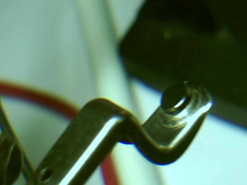
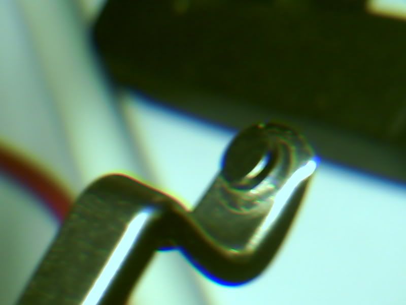
its as strong as factory job. yayLast edited by **~Imhotep~**; 06-03-2008, 04:56 AM.Leave a comment:
-
Just wanted to share a bit of info I found in the overunity forums for you Imhotep and others researching this.
Quote from post of someone who produced a larger Bedini device from this thread: Bedini replication in Germany
Most interesting: This machine will also produce a lot of HHO gas when it is run with a water electrolysis cell. the current then drops to 200 mA. There is definitely a connection between the bedini pulse and the Stan Meyer water splitter.Leave a comment:
-
just leave a message im popping in and out 24/7 to check on messages. Support will be there.

Leave a comment:
-
Been watching the progress great work **~Imhotep~**
i have got 4 fans coming 24v dont now the amps
may need support **~Imhotep~**
cant wait to see the ossilascope on this stuff
Take CareLeave a comment:
-
elcman, check out the free energyfreebe i just posted. A nice little gadget to play with, with your fan.
Last edited by **~Imhotep~**; 06-02-2008, 08:42 PM.Leave a comment:
-
the current draw on these fans are very low, when you hook them up to a charge battery the current draw drops even more ,so the source battery will sometimes last days according to the source capacity of the source battery.
in this config. the source batt. is not conditioned as far as i can tell.
because conditioning is cold spikes going in to batt. and that is on charge side of circuit.
as far as being stunned at the result i never would have put so much time in something if i was not floored at the results sofar.yay!
have fun learning and expanding your power of knowledgeLeave a comment:
-
monpole is bendini design maximizes successive pulses one way, simple explanation
ask him for detail (in his books movies etc)
to deep for post
as far as taking out neon ,you can but that would be your experiment .have at it .
when i first did this experiment ,i can show you many ways this will not work
but it was not a waste because i learned from the failures.
the neon is for your transistor to be protected from accidental charge battery disconnection or swapping batts etc..
as far as more detail thats a good idea i will include even more detail next time
Leave a comment:
-
the coil part of these schematics is generic (just indicating positive end of wrap and negative beginning of wrap and where on schematic bendini wired his ssg)
the diode off the collector will only let pulses go one way .as far as where your posts end up it might be different but as long as the end of wrap (outside of coil goes to the area indicated on schematic you will maximize the use of the coil
collapse voltage which is 100 times the voltage input yay) thats where you get the freebe.
which in the orig. circuit boards they prevent that voltage from getting out so you can use it.Last edited by **~Imhotep~**; 06-02-2008, 06:07 PM.Leave a comment:
-
as long as it worksOriginally posted by elcman View Post if you series 2 or more you will have to pay more attention to geometry of windings . but on many in parallel as long as it outputs volt of correct polarity it good to go
Leave a comment:
-
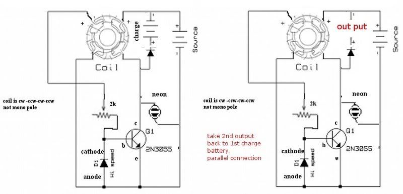
this is parallel out config for two fans it, raises potential volt and current.
i have paralleled 6 together no problem .
i am working on 12 output
the current is limited to the total potential of the fans original current draw ,which is on the labels on the back of the fans, added together per # of fans used.
the series is another story, because the circuit would have to run through the coils of each fan in series , i will be working on that version soon (reduce circuit components etc...) could become quite powerful possibly 8 to 16 poles then parallel a couple of them.
happy experimentingLast edited by **~Imhotep~**; 06-02-2008, 06:10 PM.Leave a comment:
-
One quick question, Imhotep?
I'm looking at the diagram and I have wired mine ... differently?
The fan, I assumed, the direction it turned would create a positive currently left to right. In thinking that... well, let me attach a diagram.
(See Attached)
I checked to see which ones would give me an ohm reading, then I did an inline + to - assumption between those two based on which way the fan turned.
I am getting results. I'm curious if it is just a fluke? Let me know...Attached FilesLeave a comment:
-
Leave a comment: