This forum is preserved as a permanent archive. The community continues at eMedia Press.

Announcement

Collapse
No announcement yet.

Free Energy At Last Step By Step Must See

Collapse
X
 
  • Filter
  • Time
  • Show
Clear All
new posts

  • **~Imhotep~**
    replied


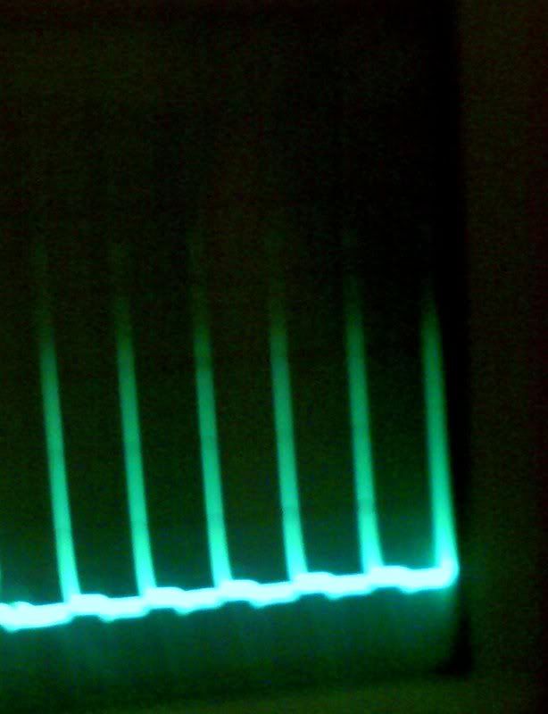
    Camera doesnt do the oscilloscope justice, but its averaging 250 volts per spike. One of my better fans. Thats the fan i will be using to charge the caps for aarons water spark plug experiment. Yes the fans have many uses. It takes about 4 seconds to charge a 250volt 680 uf cap.

    Leave a comment:


  • **~Imhotep~**
    replied
    Originally posted by Philosopher View Post
    Imhotep,
    Thanks of the help.Probably my battery is sulfated one.I'm not able to make it to retain the charge using a common battery charger.It discharge fast .
    Last night I left your fan charger working on it.In the morning I got full charge,about 6,5V(I'm sorry,but this time I have not monitored the time charging...).But I disappointed when I measured the amps.My digital multimeter started from 6-7 amps and want down after few seconds.Resembled like I was discharging a capacitor.Too fast to read the exact values;however I did not expected such amperage(overcharge?).Now,I dont know how I can go on....
    do not be discouraged with quick drain of current . keep draining battery with a 6 volt lamp and repeat process many times to see if you can increase time to drain current
    .
    my 10 amphour 12volt lead acid battery i conditioned raised in capacity over a couple of weeks ! give it a chance to charge -discharge cycles before you evaluate battery.

    Leave a comment:


  • Philosopher
    replied
    Imhotep,
    Thanks of the help.Probably my battery is sulfated one.I'm not able to make it to retain the charge using a common battery charger.It discharge fast .
    Last night I left your fan charger working on it.In the morning I got full charge,about 6,5V(I'm sorry,but this time I have not monitored the time charging...).But I disappointed when I measured the amps.My digital multimeter started from 6-7 amps and want down after few seconds.Resembled like I was discharging a capacitor.Too fast to read the exact values;however I did not expected such amperage(overcharge?).Now,I dont know how I can go on....

    Leave a comment:


  • **~Imhotep~**
    replied
    Originally posted by Philosopher View Post
    [ATTACH]830[/ATTACH]

    Here my complete unit.
    I'm chargining a 6V 4Ah lead acid battery.Can you axplain me the Bedini rules for the correct discharge of this battery?Thank you.

    Excellent. Text book example. Thanx for sharing. Keep in mind that if the battery was sulfated or drained enough it could take literally days to charge it back up. As far as draining, if it was a 12 volt you would merely hook a invertor to it. However since you are using a 6 volt, what i would do is use a standard lamp bulb from a 6 volt lantern (walmart 3 dollar one) and wire the battery to it with clip leads or whatever. Some people have to cycle the batteries several times before they are conditioned where they retain the most amount of charge. For example :

    The wife has a small dollar tree lcd clock on her desk, when we first started this project about a month ago, she kept handing me batteries to charge for her. after about 3 to 5 charges the alkaline battery that the clock uses was conditioned enough so that it has been running the lcd clock after a 120 second charge for about 4 to 5 weeks now. We are wondering if it will ever drain. So conditioning the batteries is very important.

    Please watch this video if you haven't all ready :
    http://www.energeticforum.com/renewa...ls-plates.html

    and my thoughts on it are, he is not only showing you how to make an alkaline battery but he is also showing what these radiant chargers does to the crystal structure of lead acid batteries. What it appears to do instead of making large crystals with high current that eventually shorts out the battery, and prematurely sulfates them, he uses the high voltage lower amperage spikes to condition the plates to make very small fine crystals that dont short as easily or as quickly, and then uses a low current conventional charge and it appears to show once the batteries are conditioned you can actually get more energy out on a timed interval than the time interval of charging. For example : he charges his homemade lead acid battery for one minute and then loads it down for 3 minutes, drawing the same current he put into it. Showing that the batteries will last longer once they are conditioned. That is strictly using the conditioning mode of these radiant chargers. Some people are mistaken in the fact that they think they are going to get a long term ability out of batteries that are charged with these small fans. You can charge them with a adjustable current and voltage power supply after they are conditioned and get astounding results out the conditioned batteries, you can also charge them directly with the fans but it will take a long time to get the full capacity with the larger size batteries. As well as conditioning lead acid batteries i have taken batteries zinc carbon, and alkaline that where ready for the garbage and directly charged them with the fans and been able to run loads again, that to me was very valuable in emergency situations. Where power outages occur and you cannot go to the store to buy batteries, where you can hook one of these fans to your car battery and they draw very small amps, and you can charge up a handful of batteries to use for your radios and mp3s players and such to stretch a little more energy out them, multiple times. May uses. again yours is one of the best ones i have seen, neat and accurate very well done. Looks a little cleaner and neater than any of mine actually. good job!!!

    Leave a comment:


  • Philosopher
    replied
    Click image for larger version

Name:	IMG_1180.jpg
Views:	1
Size:	260.4 KB
ID:	445151

    Here my complete unit.
    I'm chargining a 6V 4Ah lead acid battery.Can you axplain me the Bedini rules for the correct discharge of this battery?Thank you.

    Leave a comment:


  • noob
    replied
    Originally posted by **~Imhotep~** View Post
    you can use a 3300 mf 200v cap, run from that to battery it will smoth output
    new website is growing with new into to come shortly ,bigger chargers and other fe devices within weeks
    I noticed you had a video on soldering on your site. Do you have more Youtube videos to suggest for electronics noobs like me? I want to try to build your circuit but I want to get a basic understanding first.

    Thanks!

    Leave a comment:


  • gmeat
    replied
    You have me wondering

    Hi Imhotep,


    Alright, You really have me wondering about this new circuit.Could it be that your moving some Potential around .Come on,Give us a little clue .


    -Gary

    Leave a comment:


  • mikkyo
    replied
    Originally posted by Tehnoman View Post
    This ZALMAN fan is almost pain in the a**, first the stator was manufactured on the case of the fan, so the only way I managed in removing it, was sawing it out. And that's not all. These coils are bifilar, and all are connected, first and second is connected by two wires, second and third - by one... And there is no logical pattern.
    I've haven't seen a fan yet that the stator is part of the case, that does sound like a pain.
    I've seen the stator held on by glue, a snap ring in the middle on the fan side, clips on the bottom, a rotate and lock method, and the worst so far, 4 clips on the bottom which ideally need a 4 prong tool to release while pulling on the stator (I managed with 4 small screwdrivers and friend's help).

    As for windings, I don't know if you checked electrically or magnetically, but many of the stators I have looked are deceptive with regard to where the wires run.
    On the ones I have with the 2 opposite coils connected, the wire from the first coil runs under the adjacent coil but isn't a part of it. The second coil then has wires that run to the opposite coil under the 3rd coil, so it looks quite confusing.
    One bifilar one has 2 connections on the first coil, one for it, and one goes to the 3rd, the second also has 2 connections, 1 to it and one to the 4th, so same as the single wire one I described, but with 6 wires running behind the 2nd coil had me confused for a long time.

    I guess you could maybe test the wires and move a magnet over the coils and see which coil generated a charge in what wires.

    Leave a comment:


  • **~Imhotep~**
    replied
    you can use a 3300 mf 200v cap, run from that to battery it will smoth output
    new website is growing with new into to come shortly ,bigger chargers and other fe devices within weeks

    Leave a comment:


  • mikkyo
    replied
    I've made 5 different brushless fan SSGs, and so far all the batteries I have tried to recharge have not held a charge.
    I can get them up a few volts above their rated voltage after a long time on the fan SSG, but in the end once disconnected they can't power a load for long.
    I've done lots of reading online and it seems some folks have better luck with a capacitor hooked up with the output battery.
    Has anyone else had success with or without a capacitor and if so what values of components are you using?

    Leave a comment:


  • **~Imhotep~**
    replied
    i have not ran into that type of winding ,my thoughts were when i started my fans was to get all of them going and i have . some i rewound with cw ccw cw ccw bi filler wind and they worked fine with the existing magnetic structure . i have thought about pulling the magnetic strip off one in the future and giving steel strips a try just to see if they will still run with no back emf to lower current draw even more and just use coil collapse spikes( attraction motor mode )it is just an idea i might try . if it works i will post results. i am super busy right now with web site and other projects .have fun learning and never give up ! i will be dropping in to check on thread as i can.

    Leave a comment:


  • Tehnoman
    replied
    Thanks. So the resulting wiring I understand correctly.

    But oh. This ZALMAN fan is almost pain in the a**, first the stator was manufactured on the case of the fan, so the only way I managed in removing it, was sawing it out. And that's not all. These coils are bifilar, and all are connected, first and second is connected by two wires, second and third - by one... And there is no logical pattern. And all 4 coils are connected to only 3 connectors. Two combinations have resistance of about 26 ohms, other one - twice as much (~ 52 ohms). Have some thoughts, but need further work.

    Yesterday I finished modifying old PC PSU, so I can get DC current. So when I'll have time, will try to understand my fan further.

    Although ZALMAN is good fan manufacturer, their production is not the best to customize.

    Leave a comment:


  • **~Imhotep~**
    replied
    yes you are correct ,the picture i used was generic. the existing coils are wound this way on most dual phase series wound dc servo fans .i found some were single wound and some were bi filler (two winding together).

    Leave a comment:


  • Tehnoman
    replied
    Originally posted by **~Imhotep~** View Post
    more detailed schematics and magnified stator.

    Ok. As many in this thread, I also have started to build this device. Yet I have disassembled my PC fan (I found in my home two unused ZALMAN ZM-F3 120mm quiet fan) and now I'm thinking about how to reconnect coils (despite the fact I can't figure out how they originally was used).

    Question - do I have to connect trigger "+" coil and trigger "-" coil together, and in similar way also power coil?

    My intuition says - I have to do it.
    But in your picture all coils are separated?

    Sorry, If this has been answered before, didn't find direct question about it in this thread. Although I have read it all.

    There is my edited version of your stator:


    Of course, connections must be made correctly, keeping in mind our rotor magnetic configuration...

    Leave a comment:


  • **~Imhotep~**
    replied
    Originally posted by mikkyo View Post
    The stator coil layout in the dual transistor circuit looks just like the fans I've been using.
    It looks like one just needs to add a tap on 2 of the coils so they can be driven individually.
    I think I'll give it a try.
    i believe that was the tape drive motor that bedini gave rick, but if your magnets are the same it should have great spikes

    Leave a comment:

Working...
X