This forum is preserved as a permanent archive. The community continues at eMedia Press.

Announcement

Collapse
No announcement yet.

Free Energy At Last Step By Step Must See

Collapse
X
 
  • Filter
  • Time
  • Show
Clear All
new posts

  • theremart
    replied
    Originally posted by CitizenDC View Post
    Hello Guys,

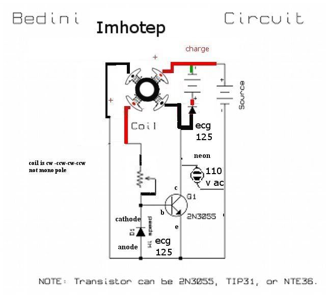
    I've started replicating Imohteps fan SSG. I'm busy sorting out `what goes where` .

    I've read through most of this forum to ensure I do this right.
    Two questions I have, I hope someone can shed some light on for me.

    1. Do I understand correctly that the fan's PCB is eliminated from the design?
    Meaning, that its not necessary to use the PCB the fan came with?

    2. Is it essential to have a fan with coil to coil resistance of at least 40ohm in order for the fan to spin up with this circuit? Would a larger fan of say 2.5ohm from coil-to-coil work?

    Many thanks to all!
    1. Yes unsolder it and remove it.

    2. Fans have been made for up to 24V.. It does sound reasonable to me that a larger fan would work...

    Great videos on Imohteps site... for step by step how to build...

    Keep going don't stop!

    Leave a comment:


  • CitizenDC
    replied
    Hello and Help : )

    Hello Guys,

    I've started replicating Imohteps fan SSG. I'm busy sorting out `what goes where` .

    I've read through most of this forum to ensure I do this right.
    Two questions I have, I hope someone can shed some light on for me.

    1. Do I understand correctly that the fan's PCB is eliminated from the design?
    Meaning, that its not necessary to use the PCB the fan came with?

    2. Is it essential to have a fan with coil to coil resistance of at least 40ohm in order for the fan to spin up with this circuit? Would a larger fan of say 2.5ohm from coil-to-coil work?

    Many thanks to all!

    Leave a comment:


  • **~Imhotep~**
    replied
    It still is coming. I am currently fine tuning and gathering my data for the video for it. I should be releasing it within the next week or so

    Leave a comment:


  • Dingus
    replied
    You once said that you were working on a simpler charger than the fan motor. Just wondering if you forgot about it(or if I overlooked it) or did you put it aside to work on your radiant oscillator?

    Leave a comment:


  • **~Imhotep~**
    replied
    Originally posted by Pcurrius View Post
    I've fullfil this working...but I'm not sure properly. First of all I use a 12V (actually mesured 16 V) power supply when I turn on the fan giving a little force to turn begin to turn a rarely low rpm's. Then the strange thing is that I wait 60-100V between emisor collector and there are 12V. Maybe is because I don't use an scope and I'm using a multimeter, could be...? My charge battery is charging but very slow. Also when I tried to change my power supply for a conventional battery seems that is working but the fan stops (maybe because needs more power? the battery is around 10V). Don't know what's happening...some help?
    Can I recharge some Zinc or some kind of alkaline cell with that type of energy?


    PS: I supose that B+ is the conjution between the positive and negative of the supply and the charge respectively.
    you can charge carbon -zinc and alkaline and ni-hm and lead acid batteries and large capacitors , you can use digital meters and they will sometimes read in the hundreds of volts sometimes but that is the hv spikes be careful on charging zinc carbon and alkaline cells after a dozen charges i have had them leak so now if i charge disposable batteries i put them in a separate container and wire clips to the items i want to use them for,so it dosn't get messy if they leak after multiple charging good luck . also if you get low rpm on the fan adjust pot or increase source voltage.

    Leave a comment:


  • Pcurrius
    replied
    strange working...

    Originally posted by **~Imhotep~** View Post

    ok at the power coil hookup and the trigger coil hookup exactly .
    you have it miss wired change your wiring and you should be successful one side of trigger to POT other side to EMITTER one side of coil for power to COLLECTOR and other side to B+
    I've fullfil this working...but I'm not sure properly. First of all I use a 12V (actually mesured 16 V) power supply when I turn on the fan giving a little force to turn begin to turn a rarely low rpm's. Then the strange thing is that I wait 60-100V between emisor collector and there are 12V. Maybe is because I don't use an scope and I'm using a multimeter, could be...? My charge battery is charging but very slow. Also when I tried to change my power supply for a conventional battery seems that is working but the fan stops (maybe because needs more power? the battery is around 10V). Don't know what's happening...some help?
    Can I recharge some Zinc or some kind of alkaline cell with that type of energy?


    PS: I supose that B+ is the conjution between the positive and negative of the supply and the charge respectively.
    Last edited by Pcurrius; 08-06-2008, 03:47 PM.

    Leave a comment:


  • **~Imhotep~**
    replied
    Originally posted by Tehnoman View Post
    So.

    Got it working!!!

    There was two things.
    1) About DC resistance - true, previously I had connected bifilar windings parallel, that means - lower DC resistance and possible higher current flow. Don't know, why I did it, but I was wrong. Reconnected wirings in series, got 4x initial DC resistance and at least some neon activity, when I spin the fan. But that was not the whole story.

    2) My rotor magnetic accidentally got messed up, when I tried to find out magnetic configuration. That was because I used too strong magnet too close to rotor, to see the N-S configuration. Have absolutely no idea, why.. Changed the rotor to identical one from my other fan and spinning went off.

    So far looks good. Sounds a little bit strange, but current draw is nice and low... Between 50 and 120 mA. Will try to post some pictures and maybe video of my device tomorrow.

    P.S. Wire bifilar coils in series and don't stick too powerful (neodymium as in my case) magnets to stator. Will mess things up.
    The stator is laminated steel and its magnetism changes ever pulse of the coil it should not be magnetized at all the ceramic strip on the rotor is the magnetic structure of the motor and you can take a 16 penny nail and touch it at various points on the center of the ceramic strip and then take the nail and hold that up to a compass and i believe whatever indication is on the compass would be the opposite polarity of the magnetic strip. I told a few ppl if they wanted to check the magnetic structure of the fan that was one way i had done it. But almost all fans that i have encountered had a complex magnetic structure as to not have any dead spots on the original circuit startup configuration.

    In other words, when you have the original circuit on these fans they had made the magnetic structures with 3 bands and the center of it had the largest band and it was north, south,north,south arrangement. Then a very thin strip at the bottom had 8 north, souths instead of 4, like the center, and that was just so there was no dead spots when the fan started up in the auto start mode. But we manual start these when we remove the circuit. So the only magnetic band you need to be concerned with is the center of the ceramic band. But by all means NEVER magnetize the rotor.

    Its all a learning process.

    Leave a comment:


  • Tehnoman
    replied
    Yeah, I know that. That's why I said - I have no idea why I did it. I know, how old, "depleted" permanent magnets are renewed with help of strong magnetic field. I am physics student after all...

    When I destroyed one of my rotors, I guess I could have been dizzy... Don't know. Maybe my logic took free day.

    Leave a comment:


  • Jetijs
    replied
    Tehnoman,
    those rotor magnets are not very strong. When you put a strong neo magnet near such a weak magnet, the stronger magnetic field will overcome the weaker field and change it. This way you can change the weaker magnet polarity or seriously distort the magnetic field of the weakest magnet. I did this once, I put a strong neo magnet on top of a ceramic magnet so that both N poles were facing each other. At first they tried to repel each other, but then the strongest magnet took over the weakest magnet and they stacked together. After this you could see how the field of the ceramic magnet was distorted using a magnetic field viewing film

    Leave a comment:


  • Tehnoman
    replied
    Originally posted by **~Imhotep~** View Post
    ohms is extremely low my coils had 30 to 60 ohms dc resistance if all of your parts are good and wired correctly ,the low ohm could be you problem,
    [..]
    So.

    Got it working!!!

    There was two things.
    1) About DC resistance - true, previously I had connected bifilar windings parallel, that means - lower DC resistance and possible higher current flow. Don't know, why I did it, but I was wrong. Reconnected wirings in series, got 4x initial DC resistance and at least some neon activity, when I spin the fan. But that was not the whole story.

    2) My rotor magnetic accidentally got messed up, when I tried to find out magnetic configuration. That was because I used too strong magnet too close to rotor, to see the N-S configuration. Have absolutely no idea, why.. Changed the rotor to identical one from my other fan and spinning went off.

    So far looks good. Sounds a little bit strange, but current draw is nice and low... Between 50 and 120 mA. Will try to post some pictures and maybe video of my device tomorrow.

    P.S. Wire bifilar coils in series and don't stick too powerful (neodymium as in my case) magnets to [not stator] rotor (sorry, fast typing mistake). Will mess things up.
    Last edited by Tehnoman; 08-06-2008, 09:16 AM.

    Leave a comment:


  • **~Imhotep~**
    replied
    Originally posted by Pcurrius View Post
    Hey.

    First I have measured the continuity of the coils (40-50) each pair. Then I choose one continuity as a trigger coil (in my case blue wire), one side positive, the other side negative. I connected one side to the potentiometer and the other in the collector. The other pair of coils (brown wire) I've connected one to the positive of the source and the other to the negative (emitter of the transistor). Then I turned on the source, and my fan at 2k has a contrary force if I try to turn during quarter round and correct force if the other quarter of the round. I've tried many fans and all work same way...I don't know where I'm wrong. I tried interchanging the blue wires to change the direction of the current. Nothing change...
    I may have hooked wrong the circuit...now I don't know what's happening. If I don't find the solution I'll try to wind the coils by myself.

    Thanks in advance.

    PS: Just seen that my charge battery was disconnected


    ok at the power coil hookup and the trigger coil hookup exactly .
    you have it miss wired change your wiring and you should be successful one side of trigger to POT other side to EMITTER one side of coil for power to COLLECTOR and other side to B+

    Leave a comment:


  • energeist
    replied
    It Works

    For everybody out there trying to get it to work! keep trying! It works and if I could do it, oh god, so can you!! I am a complete illiterate in electronics and it took me ages to make sense of the circuit plan, and yet my fan is spinning for days now, the powering battery still far over 12 volt(bought a new 12 volt, 12 ah), and by the looks of it, it charges more than it looses (i am still testing and I will release my results shortly)

    Imhotep you totally rock, so does rick friedrich certainly, well and the godfather of all that, John Bedini: I research about you now for more than a year and never stopped

    Mr. Lindemann, for your devotion and your abilities to teach my deepest thanks. You gave me Gerri Vasilatos!!!!!!

    My next step is to make the batteries switch, so there is a fan that spins forever, people need to touch and see to start thinking! Does anybody have a circuit plan for this?? Also, is it possible to attach a little load on th sg like it is with the more sophisticated bedini generators?

    Anyways, I am proud and happy to be a member on this forum, you all are great!!!

    Leave a comment:


  • Pcurrius
    replied
    Not working yet and don't know why :S

    Hey.

    First I have measured the continuity of the coils (40-50) each pair. Then I choose one continuity as a trigger coil (in my case blue wire), one side positive, the other side negative. I connected one side to the potentiometer and the other in the collector. The other pair of coils (brown wire) I've connected one to the positive of the source and the other to the negative (emitter of the transistor). Then I turned on the source, and my fan at 2k has a contrary force if I try to turn during quarter round and correct force if the other quarter of the round. I've tried many fans and all work same way...I don't know where I'm wrong. I tried interchanging the blue wires to change the direction of the current. Nothing change...
    I may have hooked wrong the circuit...now I don't know what's happening. If I don't find the solution I'll try to wind the coils by myself.

    Thanks in advance.

    PS: Just seen that my charge battery was disconnected
    Attached Files
    Last edited by Pcurrius; 08-05-2008, 09:18 AM.

    Leave a comment:


  • Tehnoman
    replied
    Well, I used existing configuration, I had to rewind only one of them, because I couldn't get out one end of wires. The wire itself is small as hell, I haven't got smaller in my home, that is for sure. Lenght of wires was ~7 m each (bifilar winding). More wire wouldn't fit in. Tomorrow I'll try to change my rotor, I have second fan (the same model). If that won't help, will try to find other fan.

    Leave a comment:


  • **~Imhotep~**
    replied
    i will be posting a video in the next few days demonstrating how to wind the poles on my website Imhotep's Laboratory | Renewable Energy in the faq (ssg project q and a),if you still have problems ,check for it it will be there soon and on you tube.

    Leave a comment:

Working...
X