This forum is preserved as a permanent archive. The community continues at eMedia Press.

Announcement

Collapse
No announcement yet.

Free Energy At Last Step By Step Must See

Collapse
X
 
  • Filter
  • Time
  • Show
Clear All
new posts

  • elcman
    replied
    Originally posted by **~Imhotep~**
    i am in the process of expanding the capabilities of these units rapidly (paralleling and switching) will be uploading more soon i have heard of that swapping method and will be trying soon, that would be the best method .
    some batteries are suppose to not like being switched that way, but i will test that for myself and give it a try i can get all the stock(batteries etc.) i want .
    I'm very interested in your results here. The switching seems to be a good way to keep energy flowing ... but also operating the fans in parallel and so forth, I'm... very interested in how that works out. I've been looking at things... and wondered if there was a way to operate them serially? (Though it doesn't seem at all compatible since each Bendini is self-contained...) If you could get them to phase opposite each other, it ... ? Here's my lack of experience showing.

    I'm low on funds so I'm slowing down on buying so many components until I can get a makeshift lab set up for all of this equipment. I've found my work was moving their R&D department... and a lot of surplus electronic equipment will be dumped since they're moving to a much smaller space. God, I love this place.

    So, I might be able to get my hands on an old oscilloscope and a bunch of soldering stations for free. And... likely, a ton of case fans as well. Wee!

    Originally posted by **~Imhotep~**
    you can use any power supply from from swich mode 9 volt to 35 volt i would guess but switch mode pwr supp must have load all the time, the built in fans usually on computer supples furnish that . so i would leave the unaltered fan inside if you try.
    The system I was looking at actually used a ~10 Ohm resistor to create a constant load as well as an LED to show that the thing was switched on. It looked to be a pretty ingenious design also allowing for a variable voltage add on... the one thing I'm not sure on is the amps.

    I have been doing a crash course on electronic components to make sense of schematics. I really need to study electric and electronic "theory" ...

    Before it teaches me.

    Originally posted by **~Imhotep~**
    i use a variable supply 0-36 volt, i redesigned it to have current regulation as well as voltage regulation .
    Yeah, that's what I'm shooting for. I'm hoping this will do the trick:

    How to Convert a Computer ATX Power Supply to a Lab Power Supply - wikiHow

    Then:

    How to Add Variable Voltage to Your ATX Based Bench Power Supply - wikiHow

    Exciting! And a little dangerous. Just need some additional components before I can attempt it.

    Originally posted by **~Imhotep~**
    have fun and post data (share) results
    You've got it! In fact, a strange thing happened last night...

    I've been reconditioning one battery at a time with my one functioning fan. Of course, it's taking a while for it to work properly, so I switched over to a car battery I found in my garage over the weekend. It immediately took a charge, so I let it go for a while, coming back often to check for heat, "bulging" and other signs of imminent danger. The battery accepted a charge and immediately started showing results.

    Finally, I'm getting somewhere... I had my little drill battery hooked up to it and running for a couple of hours. This is the strange thing... this little drill battery has awful capacity. It usually lasts about 2 hours.

    Last night, I went and checked on the battery 6 hours later... and it was still purring along while attached to this car battery. Was I correct in assuming that the source battery was also being "conditioned" while acting in the source position due to the charging negative being line with the source positive connection? For some reason, it really is lasting longer... even when charging off of its normal charge base.

    Needless to say, I was stunned at that result.

    Leave a comment:


  • Pcurrius
    replied
    Schematics

    Originally posted by **~Imhotep~** View Post
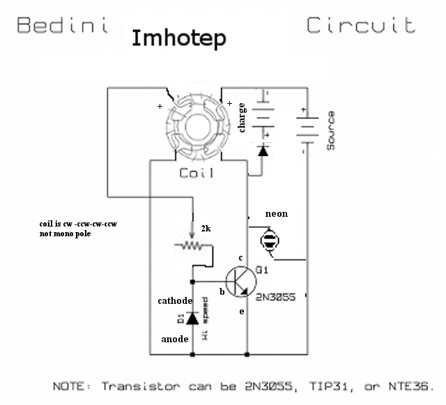
    This is revised schematic with more details. (this is not a bendini monopole motor ssg)

    Leave a comment:


  • **~Imhotep~**
    replied
    I am editing and compiling results and conclusions and uses for this implementation (imhotep) of the bendini fan with troubleshooting tips and currently simultaneously working on two other inventors mysteries which i have solved and am in the process of proving and revealing and will be releasing more movies soon.

    i will be submitting more schematics on this thread soon on paralleling output on this fan to raise power, today hopfully.
    happy experimenting

    Leave a comment:


  • **~Imhotep~**
    replied
    This is revised schematic with more details. (this is not a bendini monopole motor ssg)

    Leave a comment:


  • **~Imhotep~**
    replied
    Originally posted by Rayaz View Post
    Thankyou very much for the assistance Imhotep!

    Yes the 2 yellow are both the same side.

    Well it appears with the testing that the transistor is dead it has no reading from the pins so I will try with a new one on monday.
    while you are at it get a few, if you want to parallel output of more baby ssg's
    free computer fans are everywhere.
    i'm glad i could help, and you have gained a new skill (troubleshooting).i have made small fortune on troubleshooting skills yay!
    have fun and get some recycled energy .

    Leave a comment:


  • Bodkins
    replied
    Also Imhotep thanks this is very useful info.

    Leave a comment:


  • Rayaz
    replied
    Thankyou very much for the assistance Imhotep!

    Yes the 2 yellow are both the same side.

    Well it appears with the testing that the transistor is dead it has no reading from the pins so I will try with a new one on monday.

    Leave a comment:


  • **~Imhotep~**
    replied
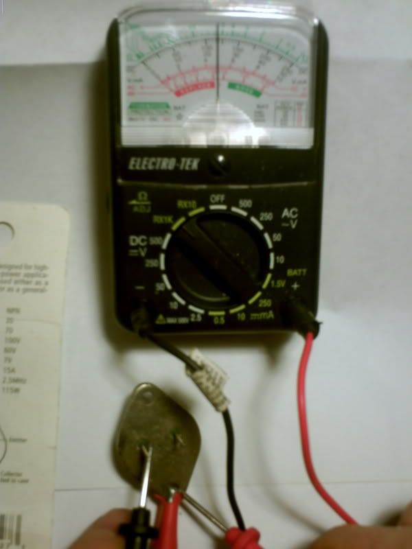
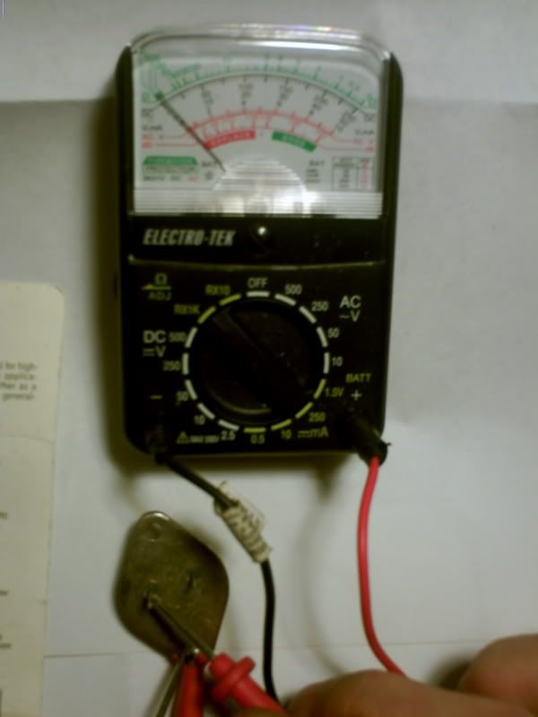
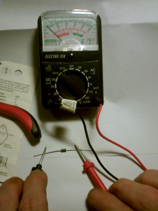
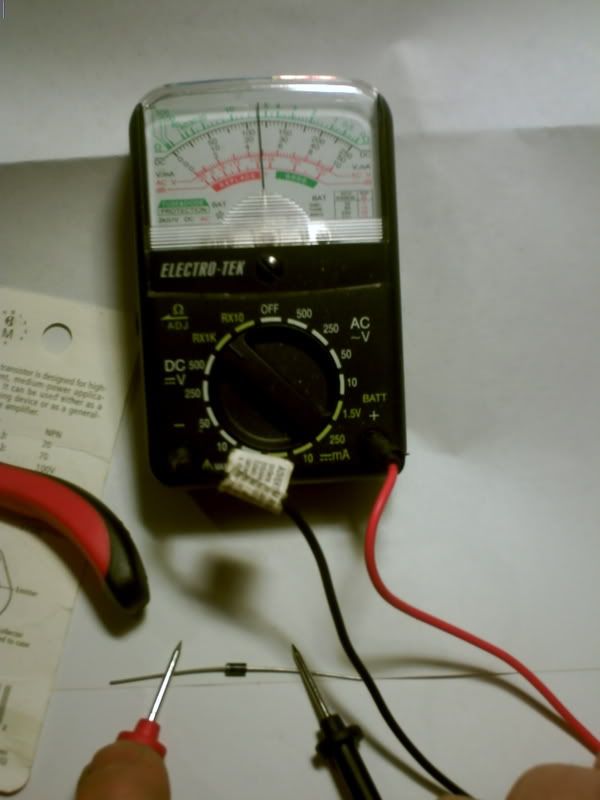
    this is if you take the measurements with an analog meter. again pay special attention to the positions of both the needle, and the leads, both red lead and black lead.


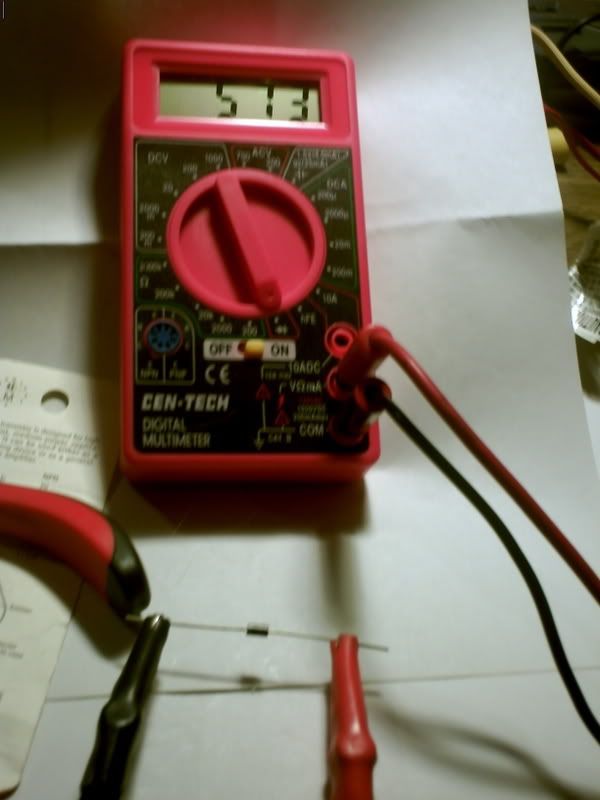
    now the diodes :


    u get the idea on the analog meters make sure you set it to rx1

    Leave a comment:


  • **~Imhotep~**
    replied


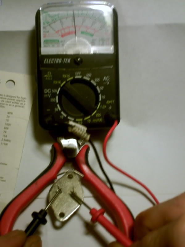
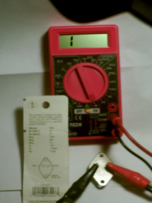
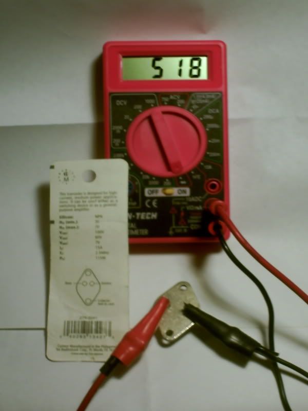
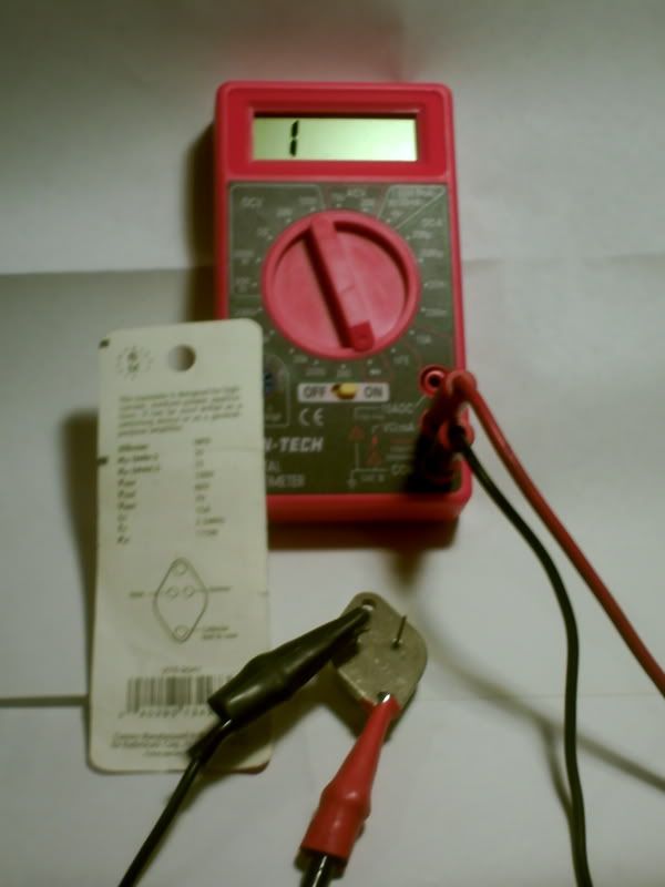
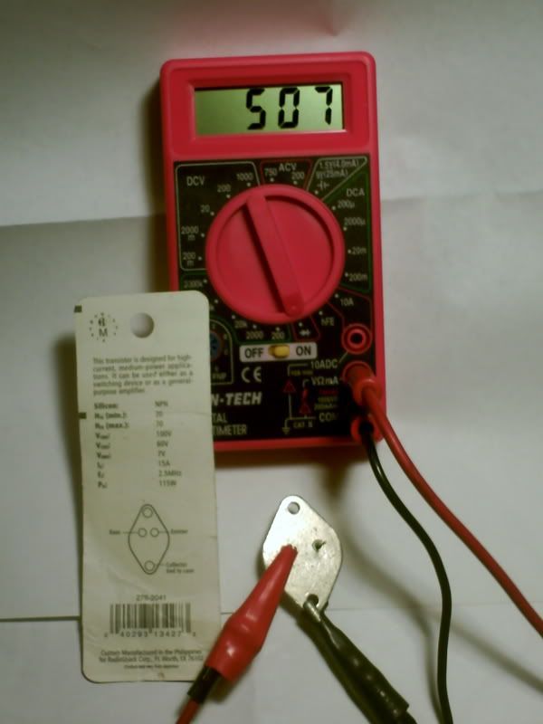
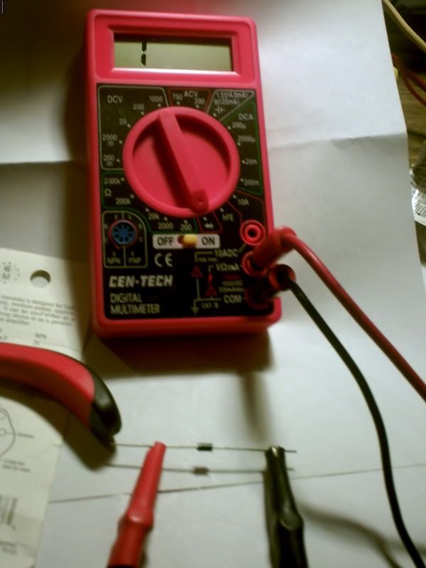
    if you have a digital meter and u put it on diode test. And the transistor is facing the way it is in the picture which is pins are closer to the top. This is what the normal (good) reading should look like. Keep a close eye on how the clips are hooked up on the transistor.(colors)


    again look at the digital read out and the way the clip leads are connected. And thats the reading of a good transistor. And the reading should stay steady.


    DO NOT BUY OPEN BOX OR OPEN CONTAINER PARTS FROM RADIO SHACK!! I HAVE AND PPL WILL BURN THEM UP AND TAKE THEM BACK AND I FOUGHT MY FIRST FAN WITH A BAD TRANSISTOR I BOUGHT FROM RADIO SHACK!!! ONLY SEALED PACKAGES
    set digital meters on diode setting (diode pix on dial)
    Last edited by **~Imhotep~**; 06-01-2008, 06:16 AM.

    Leave a comment:


  • **~Imhotep~**
    replied
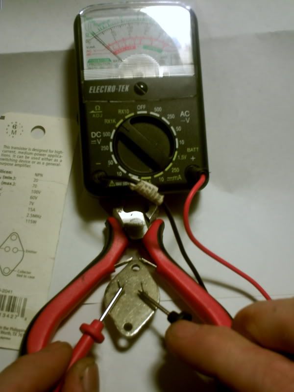
    hookup is correct.make sure your clip leads arent shorting to the case of the transistor. (only on pins, going on emitter and on the base) clips are ok for temp hookup. your hook up looks good, if the red and black wires are one set of coils. And the 2 yellow wires are another set of coils. (you might want to put a knot on one of the ends if you used the same color. if the red and black wires have good continuity 10 to 60 ohms, try reversing the clip leads. move the yellow clip to the red wire and the white clip to the black wire. if after you switch those and the fan still does spin up, the most likely you have bad parts somewhere in the circuit. I will be sending pictures on how to test the transistor and diodes.

    Leave a comment:


  • **~Imhotep~**
    replied
    Originally posted by Rayaz View Post
    Should the reading only show up for a split second when I connect the probes from the meter to the transistor/diodes? Because thats what is happening on the diodes, it is not a continuous reading.

    Also there is no reading between the pins on the transistor not even for a split second, just a reading between the base and the case. Does this mean that I fried it?


    Here are images of my circuit so you can see what I have going on here.


    i will be uploading instruction now ! it will include pix with some explanations and should help

    Leave a comment:


  • **~Imhotep~**
    replied
    Originally posted by elcman View Post
    I haven't been able to focus on this like I've wanted to, but I had nearly a dozen other things come up that have been occupying me.

    I've been readying my garage in prep for a garage sale... As soon as I can clear that place out, I'm going to figure out how to get power in there and make a mini testing lab. (As per the discussion with the batteries potentially blowing up, my wife has been eying the humming fan with a bit of paranoia.)

    If the garage blows... GREAT!

    In any case, I've gotten two lead acid batteries to start taking charge, these are not the same as the first two UPS batteries I had. These took a charge immediately, so I'm been working with them to get these batteries conditioned. It's funny... the battery's condition is just as important as anything else in this process... something I didn't quite expect, but it makes sense.

    I also found, while cleaning out my garage, 3 other car batteries that have been sitting fallow. I know two of them worked fine up, but were replaced due to age and not easily starting in winter. As soon as I can get a consistent battery that can be recharged quickly, I am going to work on the rest of these.

    Here's a question about a switching circuit... You all have been talking about making a circuit that will feed the source battery when the charging battery is "done" in order to maintain the cycle. Is it possible to switch the energy input between batteries rapidly? (Timed to every revolution or half revolution?) If the charging battery has enough charge to turn the fan, it should continue without trouble, but the momentum of the fan may also compensate for this switching motion as well. (Of course a dead battery will act like you just turned the potentiometer all the way up.)

    But if you could check the charging battery to make sure that there was enough energy to do this switching motion, then you could condition and charge both batteries.

    Does that sound like a possibility? Since I really don't have a conditioned battery yet, developing a method that would condition both would be handy.

    Ah well, I need to make another fan or 3. I'm also looking into that converting an ATX power supply to a Workbench DC Power Supply... That'll save me from running from one rechargeable drill battery over and over again.

    Good times.
    i love the great moto i am in the process of expanding the capabilities of these units rapidly (paralleling and switching) will be uploading more soon
    i have heard of that swapping method and will be trying soon, that would be the best method .
    some batteries are suppose to not like being switched that way, but i will test that for myself and give it a try i can get all the stock(batteries etc.) i want .

    you can use any power supply from from swich mode 9 volt to 35 volt i would guess but switch mode pwr supp must have load all the time, the built in fans usually on computer supples furnish that . so i would leave the unaltered fan inside if you try.
    i use a variable supply 0-36 volt, i redesigned it to have current regulation as well as voltage regulation .
    you can use the little wall plug in types (0-36 volt dc) as long you check your current draw on your fan (after alteration ) make sure your power supply has a little more than what you draw.
    have fun and post data (share) results

    Leave a comment:


  • elcman
    replied
    I haven't been able to focus on this like I've wanted to, but I had nearly a dozen other things come up that have been occupying me.

    I've been readying my garage in prep for a garage sale... As soon as I can clear that place out, I'm going to figure out how to get power in there and make a mini testing lab. (As per the discussion with the batteries potentially blowing up, my wife has been eying the humming fan with a bit of paranoia.)

    If the garage blows... GREAT!

    In any case, I've gotten two lead acid batteries to start taking charge, these are not the same as the first two UPS batteries I had. These took a charge immediately, so I'm been working with them to get these batteries conditioned. It's funny... the battery's condition is just as important as anything else in this process... something I didn't quite expect, but it makes sense.

    I also found, while cleaning out my garage, 3 other car batteries that have been sitting fallow. I know two of them worked fine up, but were replaced due to age and not easily starting in winter. As soon as I can get a consistent battery that can be recharged quickly, I am going to work on the rest of these.

    Here's a question about a switching circuit... You all have been talking about making a circuit that will feed the source battery when the charging battery is "done" in order to maintain the cycle. Is it possible to switch the energy input between batteries rapidly? (Timed to every revolution or half revolution?) If the charging battery has enough charge to turn the fan, it should continue without trouble, but the momentum of the fan may also compensate for this switching motion as well. (Of course a dead battery will act like you just turned the potentiometer all the way up.)

    But if you could check the charging battery to make sure that there was enough energy to do this switching motion, then you could condition and charge both batteries.

    Does that sound like a possibility? Since I really don't have a conditioned battery yet, developing a method that would condition both would be handy.

    Ah well, I need to make another fan or 3. I'm also looking into that converting an ATX power supply to a Workbench DC Power Supply... That'll save me from running from one rechargeable drill battery over and over again.

    Good times.

    Leave a comment:


  • Rayaz
    replied
    Should the reading only show up for a split second when I connect the probes from the meter to the transistor/diodes? Because thats what is happening on the diodes, it is not a continuous reading.

    Also there is no reading between the pins on the transistor not even for a split second, just a reading between the base and the case. Does this mean that I fried it?


    Here are images of my circuit so you can see what I have going on here.


    Last edited by Rayaz; 06-01-2008, 03:47 AM.

    Leave a comment:


  • **~Imhotep~**
    replied
    However I checked the transistor from E/B like you said and am getting no reading...
    you should have no reading that way, now switch your probes around measure the same pins. You should get a low ohms reading. Not 0 ohms, but low.

    Are transistors easy to wreck with this circuit if I had the wires set up wrong? Will it wreck it if I put the positive from the coils where the negatives should go and vice versa?
    if you use the transistor i suggested its a pretty stout one. And they are pretty hard to wreck actually. But they can be wrecked. If you hook the voltage wrong to them for any amount of time, then yes you can wreck them. They are npn's. That means negative has to go to the emitter, and negative has to go to the collector, and positive has to go to the base. They can be reversed briefly, but not for a long amount of time.

    I am thinking it wrecked when I hooked it up to the battery? Because the neon only sparked once the very first time I hooked it up and none of the times after that.
    i have had them just blink for a second for just a second when i hooked them up, and the fan blades rock. But they would still be ok. Just the transistor like i said earlier. Take your probes hook them up one way, then reverse your probes across your pins and you should have a high reading one way and a low reading the other. Theres all kinds of information online with visuals on how to test this particular transistor. Which is a t03 case. With 2 pins and the case being the collector. Its very easy to test.


    Also just checked both diodes, and am getting no reading on them either... Are they sensitive to high heat as well? I got them pretty hot with my cold/hot soldering tool even to the point where I had to set it down and let it cool off.
    Well for one thing, i dont suggest using the cold heat soldering tool. Its good for large lug type connections. But radio shack has little irons that will work just fine.
    As far as diodes, The same thing applies to them as with transistor. Take your probes, hook them one way on the diode, then reverse your probes. And check it the other way. When you have the red probe on the cathode and the black on the anode, you will have a certain resistance reading. When you reverse the probes you will have another reading. The readings should be different. If its 0ohms which ever way you put your probes on, its shorted. If there is no reading which ever way you put the probes on, then it could be open. Remember low ohms one way, higher ohms the other way when you reverse the probes

    Since I will be picking up new parts on monday now, is it ok to use a 2 amp diodes as opposed to 2.5? The store only has 2 or 3
    the 2 amps are fine. You could prob go as low as 1 amp. But 2 amp should work just as good as the 2.5 amp.


    Hi Guys,


    You guys have got to try putting a small universal motor on the back end of an SSG.I tried this with a hoover vacuum motor and talk about ZOOM had to be many thousand rpms pulling just under 1.2 amps & my cap reads a high of 16 volts at the back end of SSG .


    -Gary
    wow! share some details take some pictures and possibly video. That sounds awesome!!

    Leave a comment:

Working...
X