
Hmmm the opposite posts checked out at 20 ohms each. I did not rewind them it is the way it was set up.
However I checked the transistor from E/B like you said and am getting no reading...
Are transistors easy to wreck with this circuit if I had the wires set up wrong? Will it wreck it if I put the positive from the coils where the negatives should go and vice versa?
Or is it possible to melt the insides when soldering to the pins and wreck it that way?
I am thinking it wrecked when I hooked it up to the battery? Because the neon only sparked once the very first time I hooked it up and none of the times after that.
Also just checked both diodes, and am getting no reading on them either... Are they sensitive to high heat as well? I got them pretty hot with my cold/hot soldering tool even to the point where I had to set it down and let it cool off.
I tried alternating the nodes on my multimeter because I wasn't sure which way is right, still no reading.
edit: Since I will be picking up new parts on monday now, is it ok to use a 2 amp diodes as opposed to 2.5? The store only has 2 or 3
-
1 - are you using the original coils or did you rewind them?
A - if you are using original coils, and have four wires coming out, 2 of the wires that have continuity which should be at least a couple of ohms, will be one of your coils. The other set of wires should have a very similar reading. That is your other set coils. If that is the case where you have at least 2ohms or some single digit ohm or more but no more than 60ohms. You have the coil correct.
2 - If you rewound the coils yourself. there is instructions earlier on how to rewind them yourself. Which is 2 wires spun at least 40 times around each pole clockwise, counter-clockwise, then clockwise, then counter-clockwise
3 - if your coils are ok, then the next thing i would check, i would remove the outside circuit and check the transister with everything disconnected from it, from the base to the emitter with a ohm meter you should have a very high resistance one way and low resistance the other way. if you dont, then you might have a bad transistor. also check the diode. one way it will high resistance, the other way it wont.
(on your lowest setting on your ohm meter, which my lowest setting is 200 ohms on my meter. And dont use the higher settings on your meter always use the lowest settings. on some meters there is a diode check it will look like a picture of a diode. And you can use that setting, one way will have low digit readout and the other way high digit readout. )
If the diode or the transistor has 0 ohms,then they could be bad, and u should try substituting a different one, do not deviate from the schematic as far as the hookup of the transistor or diodes. If you are still unsure you can search the internet and you can find information on how to test a diode or transistor.
If all that checks out ok. Then hook your coils up one side of one set will be your positive input the other side will go down to the collector or case of the transistor.
The other set of coils one side will go to the either side of your adjustable vol. The other side will hook to the emittor pin of the transisitor, thats power coil
what i meant by switching the polartity, is sometimes you will have to take the wire off the second set of coils (trigger coil)and swap positions,
in otherwords the side you had hooked to the vol control you'll move that to the emitter pin and take the other wire and put it on the vol. and that about it.
dont complicate it check all your parts, the schematic is in the movie, download the movie, when you get to the schematic pause it or look at previous post, either way look the schematic over and dont be afraid to search on the internet how to test these components.
There is only a couple of components, and relax you will get them going. Ive done dozens of them and ran into dozens of problems. Sometimes you have to walk away from them clear your head an come back to the unit and look it over again. take your time and have fun. its all a learning experience. Let us know how it goes
Leave a comment:
-
Well the fan 'jerks' forward a bit but stops due to magnetic forceOriginally posted by Bodkins
I am using the one described in Imhoteps videos
I have tried spinning it up, by trigger coils do you mean switch + to - to see if I picked the right ones? I have tried. As far as I can tell I put it together properly I just tried switching the diode around between E/B because I thought I might have done that wrong but still no go.Originally posted by **~Imhotep~** View Post
When I test between the two opposite wires of each other from the coils I get 0 ohms on 2000k setting. Should they not be opposite coils? Does it have to be side by side?Leave a comment:
-
these fans arent self starters. trying spinning it up. If you have already tried this, you can switch the trigger wire coils. if you have tried that look your circuit over carefully and make sure you have all connections correct. 3 amp diode should not make a difference, might switch a little slower but thats about it. let us know.Originally posted by Rayaz View PostLeave a comment:
-
Well I got mine all put together but its not workin'.
The only things I think I did differently is I am using 3 amp diodes instead of 2.5 (it is all they had) would this cause a problem?
When I first connect the battery I get a single spark through the neon and the fan moves but doesn't spin.
Now when I connect the battery I get no neon spark but the fan moves the same but doesn't spin.
My batteries (12v 6ah and 12v 14ah) both read 13.0 V
Any ideas?Last edited by Rayaz; 05-31-2008, 10:00 PM.Leave a comment:
-
Thanks Imhotep time for me to study.Originally posted by **~Imhotep~** View Post
My set is Mr Bedini(Thank You) motor with one 12v fan with original whinding.
power one 9v battery running at 0.04amps charging one 9v
starting volts at 8.31 after full discard of primary battery,charge battery reads 8.50v
will repeat process unit charge battery volts reads 10, will them time discharge then repeat.
Good Luck everyone.Leave a comment:
-
RE: tach...
you can find them cheaper on ebay. But... it is a longer wait.
MartLeave a comment:
-
thats right! if no get a no start condition switch polarity of trigger wire, which ever coil set your using as a trigger wire set. good to go yay!Originally posted by Rayaz View Post
Leave a comment:
-
These are good tools to be safe in experimenting, and help you evaluate rpm's of fan, and temp of batteries without having to touch them and temp of motor areas and or power supplies if you using power supplies instead of batteries as a source. And a super inexpensive disposable multimeter. There are on sale right now at harbor freight for 2.99 stock up.
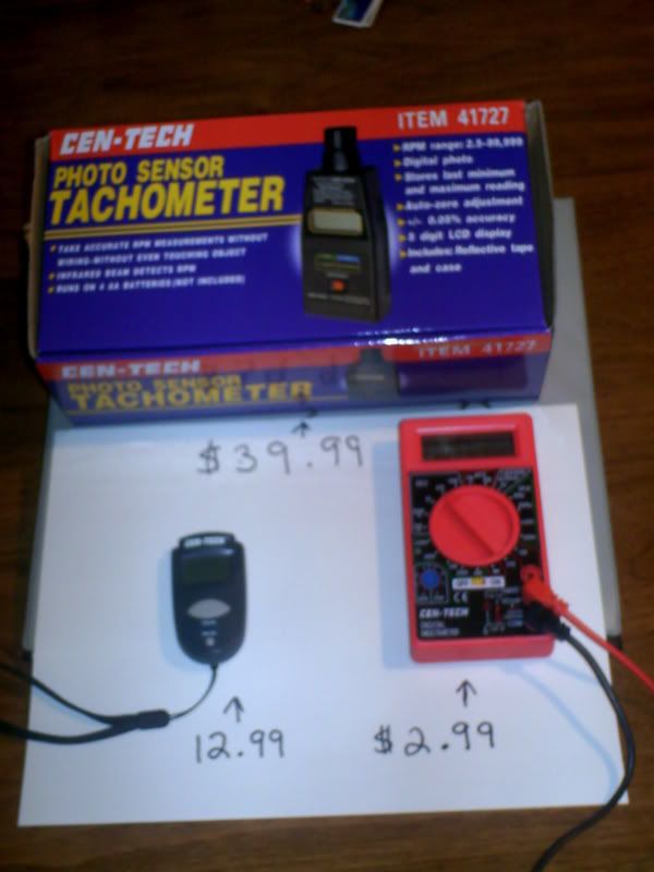
the multimeters can be used to monitor voltages and amperage, the rest are self explanatory
Leave a comment:
-
hears a starter tutorial 555 Timer/Oscillator TutorialOriginally posted by Bodkins View Post
be carefull have fun and expand capability's of this versatile machine
Leave a comment:
-
checking continuity is easy, take probes place on two of the posts on low res settings it should read 10-60 ohms if it doesn't keep probe on one of the posts and move to other ones see if you get reading if no reading move to next post if still no reading search through previous earlier entry's in this thread the mart has good vid of more tips and detailsOriginally posted by Rayaz View Post
Leave a comment:
-
thank good info!Originally posted by theremart View Post lithium pile 3 volt 8$ batts revived yay more data coming. will be sharing more
Leave a comment:
-
Safety reminders...
I have no power on this board, but I do like to share common sense I have found
1. Batteries can be bad... not a good idea to leave your experiments with certain types of batteries
Laptop battery why to be careful!!!!
YouTube - PC Pitstop: Laptop Battery Fire
Cell phone batteries
YouTube - Lithium Ion Ionen battery overcharge & explosion
Capacitors the wrong way...
YouTube - Capacitor exploding after applying excessive voltage.
General things to learn, do not use a low rated capacitor for a big job, also check the polarity of DC capacitors.
Laptop batteries and cell phone batteries on the SSG, do not charge overnite, while you are sleeping in your home.
Just some good tips..
Leave a comment:

Leave a comment: