This forum is preserved as a permanent archive. The community continues at eMedia Press.

Announcement

Collapse
No announcement yet.

Free Energy At Last Step By Step Must See

Collapse
X
 
  • Filter
  • Time
  • Show
Clear All
new posts

  • **~Imhotep~**
    replied
    the diodes are ok you need 1000 volt ,i have used 600v they were ok, the spikes that can be seen are not over 100v but i used ecg125 (4007) to be safe. as far as caps, on my parallel fan example they went to hundreds of volts within seconds without discharging or dumping into the source to help assist on self running they will keep climbing till they explode(i didnt let them go over 130v ,then discharged manually) so be careful (unless you already have your own recovery circuit, which if you do share please) i'm working on self runner now.
    the size is your choice (i used 680 mf at 200 vdc electrolytics)

    new movie should be released tomorrow on you tube and google and meta cafe and possible direct download .

    Leave a comment:


  • Pcurrius
    replied
    working problem

    Originally posted by **~Imhotep~** View Post
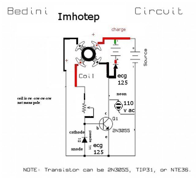
    this is the complete edited schematic new video is coming soon

    new info on movie within 24-36 hours have been sleeping for 2 days


    edit : i made a mistake in the schematics i uploaded. This is the correct one
    Good night (time from Spain) Imhotep,

    I've been working to hook up the circuit and I had working hard with the coils. They are very dificult solder without burn the plastic holder. The other difficult that I encounter is to make the forth post but I've done it with a silicon and it works good. I've hooked up all the circuit (cheking the polarity and the continuity of the coils) beeing sure that is the circuit that I have on the pick and when I connect the source (in my case an energizer of 12 V ) nothing happens. The fan didn't turn and didn't seem to being stop from any force. I have checked the continuity and the polarity of the coils so this seems to work good. I have also change one of the negative of the coils from the other one to know if this causes that the fan don't turn on, but nothing happens. Can be this because any of the components is destroyed? Do you know which can be the cause? What does the plus form the up coils means? The continuity from the coils have to be from the oposite one's is that correct? I hope so.
    If another person know the cause I'll be please the heard from them. Light and love to everyone.

    Leave a comment:


  • Dingus
    replied
    Diodes

    Ok, I have every part listed, except the diodes I have are 1.5amp & 1000V. Can I still make it, or do I need new diodes?

    EDIT: also, I'd really prefer capacitors over batteries, so what kinds of caps should I use?
    Last edited by Dingus; 06-21-2008, 10:18 PM.

    Leave a comment:


  • boguslaw
    replied
    neon

    Ok, I have seen videos.Very nice idea. I have build Bedini monopole simplified a bit larger using child bike wheel. My neon is clear one NE-2 type without casing. I see on the video there is a neon lamp used opaque one so you cannot provide information about neone color. That's what I asked.Normal color of neon is orange but with Bedini circuit it tend to be red-purplish sometimes and that's very interesting.I'd like to know what color of neon do you see when Bedini circuit imhopte type is running without load or charging battery.

    Leave a comment:


  • santhony
    replied
    Thanks imhotep

    thanks for all the help IMHOTEP.. I'll get one of these working yet....

    Leave a comment:


  • santhony
    replied
    Neon Bulb

    are there any substitutes for the NEON bulb? I'm unable to find one at a local store, and hoping I can replace with something else.

    Thanks

    Leave a comment:


  • **~Imhotep~**
    replied
    Originally posted by santhony View Post
    Can anyone confirm the coil schematic?

    I would suspect that the variations in wrappings are one of the BIG reasons people achieve different results. Since there are several variations of wraps, that I believe would work.. Also, the wrapping is the only portion of the schematics that are not listed with ABSOLUTE definition.

    Can anyone get an accurate schematic of their coil wrap posted?
    as long as you get the motor to run the details of the wrap are not that important. in this thread you will find details on various wraps ,the fans are all different so yours will differ from others ,if your fan coils are small you will get small results but you can get a few and parallel the outputs off the fans and raise the levels of recovery, also if you run off a powered supply 9-24 volts you can raise the output also ,experiment and learn from it and share, thats the whole idea.

    Leave a comment:


  • **~Imhotep~**
    replied
    Originally posted by boguslaw View Post
    Sorry,I can't find this info is such a large but very interesting topic, so I'm asking. Imhotep, do you have neone attached across C and E of 2N3055 transistor ? If so please describe how it behaves if you disconnect a charging battery or load for a few seconds.What light do you see ? Can you take a photo ? Please this is important to me.
    yes the neon will light if the charge battery is disconnected ,the closeups are on the video ,the neon shows the energy of the collapse of the magnetic field, capturing that energy is the prize.

    Leave a comment:


  • santhony
    replied
    Coil Schematic

    Can anyone confirm the coil schematic?

    I would suspect that the variations in wrappings are one of the BIG reasons people achieve different results. Since there are several variations of wraps, that I believe would work.. Also, the wrapping is the only portion of the schematics that are not listed with ABSOLUTE definition.

    Can anyone get an accurate schematic of their coil wrap posted?

    Leave a comment:


  • boguslaw
    replied
    neon

    Sorry,I can't find this info is such a large but very interesting topic, so I'm asking. Imhotep, do you have neone attached across C and E of 2N3055 transistor ? If so please describe how it behaves if you disconnect a charging battery or load for a few seconds.What light do you see ? Can you take a photo ? Please this is important to me.

    Leave a comment:


  • gotoluc
    replied
    @ITF

    Thanks for making it clear. We are on the same page

    I have been challenging these fan Bedini energizer by using very small 12v zinc batteries. The ideal is to see results in hours if not minutes since they don't have much energy reserve and are supposably rechargeable with Bedini energizers. I start with a new one at 12.5v as feed and an identical one as charge at 11.5v. The charge battery does go up and keeps the charge but not as fast as the feed battery goes down. I built 3 fan energizers, one was 80 ohms, the other 40 ohms and the last one 120mm was 4.6 ohms I did the same tests on each one and none of them were able to recharge faster than the feed battery would drain. The worst one was the 120mm a real energy hog. The one that did the best was the 80 ohm one, once I had the correct weight on the rotor (since I cut the blades) to get best balance so the rpm's don't go to high and loose neon range and also having the most resistance at the pot to keep the milliamps draw down but without losing any neon intensity. When it was tuned to its best it would draw only 19ma, the rpm's were slow, the neon is bright orange and it would squeak as it turns. I tested its charge rate and it would charge a 1,000uf cap to 32v in 10 seconds at 19ma. However it was not able to meet the above challenge. So that's all I have for now.

    Luc

    Leave a comment:


  • santhony
    replied
    Coil Wrapping Diagram

    My biggest hangup is the coil wrappings.

    Let me know if this makes any sense to everyone else, but here's how I see it.. attaching onto this messge. This was a tough one trying to draw.. But hopefully will lead to more ideas out there...

    Give it a shot.. anyone???
    Attached Files
    Last edited by santhony; 06-21-2008, 03:02 AM.

    Leave a comment:


  • InTheField
    replied
    Originally posted by gotoluc View Post
    @ITF,
    thanks for taking the time to post your test results. One thing you mentioned above that is not correct!... like you I have observe exactly as you have observed, so please let me know where I said the above so I can edit it out.
    OK... maybe it wasn't you or maybe I misread... sorry... didn't mean to put words in your post. I thought I'd read someone to say that the fan ran faster as they turned up the pot. Glad to know we're getting the same results. Again, sorry about my confusion, you'll find that happens sometimes from us who are old enough to remember slide rules.

    Originally posted by gotoluc View Post
    You are correct about the DC Resistance of some fan motor coils being lower than 40 Ohms. I have a 120mm that is only 4.6 Ohms. However it is not giving me good results, so I did not mention it. I would consider re-coilling it but first I would like to know if anyone knows the ideal DC Resistance range. I must say that I am disappointed with the lack of participation or comments in this tread.
    I think my 120mm fan read somewhere in the 4-6 ohm range. It's charging fine. Initially it was better than the 80mm fan, but not over this past week as previously posted. More results/participation/input is always better, but perhaps, like myself, sometimes "life" gets in the way.

    Originally posted by gotoluc View Post
    To all, I am bolding DC Resistance because some are using the term Impedance and from what I know and understand that is not the correct term to use if you are using your Ohm meter to measure your coils resistance. However I am very open to learning , so if anyone knows better please explain to let me know.
    Well... "kind of"... "Impedance" is a term mainly used for AC complex currents/circuits that have voltage and current, but also have phase. It is also used generically to include both resistive and reactive (caps & inductors) devices. Even though we talk about the DC voltages in this circuit, I've used the term "impedance" because of the variable pulsing and the way the circuit is setup. In AC circuits, it includes the phase which is usually a sinusoidal wave form. However, the phase term as well as the reactive component do not have to refer strictly to a sinusoidal wave. The wave could be square, saw, triangle, sinusoidal, rectified... but it indicates the fact that more than just a resistive load/effect is occurring and that there is a phase component which may or may not align with other similar signals. Strictly speaking, you're correct that DC resistance is correct when measuring the value of the coil windings. In general, impedance encompasses the resistive load too and is often used as a generic term for any LRC-like circuit. I suppose I should be more "exact" and careful when posting. I'll try harder.

    Leave a comment:


  • **~Imhotep~**
    replied
    we are currently in talks with some people about refinement on final release and will be released as soon as possible
    sorry for the delays working on other projects simultaneously
    ,trying to get all complete soon.

    Leave a comment:


  • gotoluc
    replied
    Originally posted by **~Imhotep~** View Post
    New videos being uploaded as we speak. I will post the direct link as soon as it is ready for viewing. This one is dedicated to John Bedini, Rick Friedrich, and Dr.Peter Lindemann. Special Thanx goes out to theremart for his help. Much more detail and new information.

    Hi Imhotep,

    thanks for all you have done to date I did not see the link wet to the video you are referring too. Is it ready for viewing?

    Luc

    Leave a comment:

Working...
X