This forum is preserved as a permanent archive. The community continues at eMedia Press.

Announcement

Collapse
No announcement yet.

Cap Dump Circuit

Collapse
X
 
  • Filter
  • Time
  • Show
Clear All
new posts

  • Dave45
    replied
    I cant access the ssg thread, this is more of a cap dump circuit anyway.
    Im not sure if this can be scaled or not but if it could.

    Leave a comment:


  • BroMikey
    replied
    Coils?

    Originally posted by Dave45 View Post
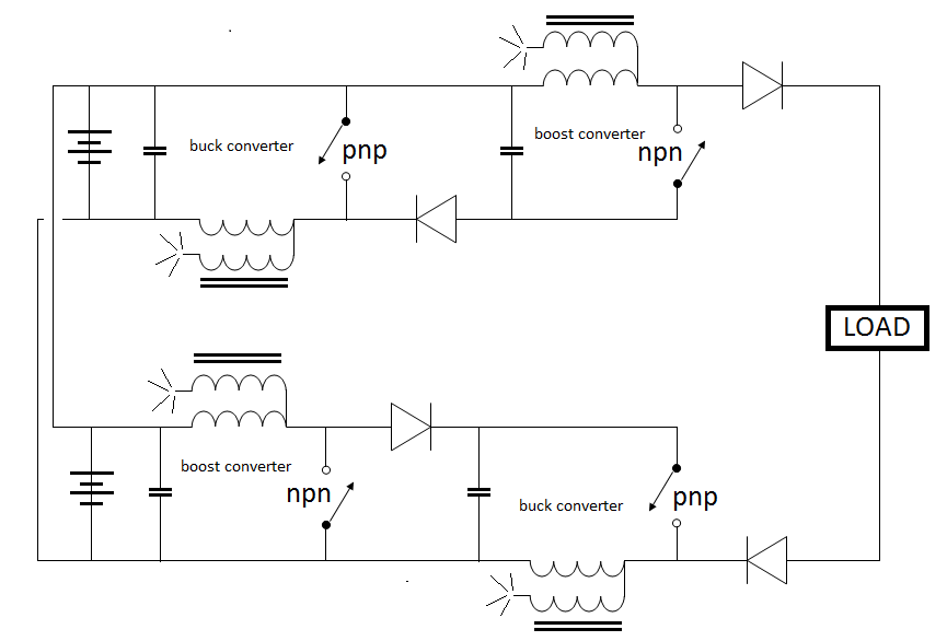
    Four separate coils Mike

    Matt gave instructions for the coils
    Thanks for the heads up I guess that solves that problem real fast.

    I will wind my own coils and anything else I need I will just ask whoever is working on this stuff. I have seen this so many times. The guys that come up with these designed don't want to do them anymore and it just sits there.

    There are basket coils and star coils, toroidal coils, Tesla coils, loose coupling, tight coupling, iron wire coils, silver coated Teflon magwire coils, stranded wire wound coils, chock coils the size of my thumbnail, coils as big as a wheelbarrow.

    Coil cores of iron epoxy, air, magnesium, nickel, chromium, and the list goes on out into Never Never-land.

    I think coils of almost any kind will work some but the core such as John Bedini has pointed out is best for radiant captures. Also coils can be put in close proximity to one another when there are four of them like this operating off the same circuit.

    SO I think the placement of the 4 coils could create a further interaction as each one might collect something from the other as the circuit runs.

    YOU GOT ME THINKIN DAVE http://www.energeticforum.com/john-b...verter-19.html

    Mike
    Last edited by BroMikey; 07-27-2014, 12:04 AM.

    Leave a comment:


  • Dave45
    replied
    Four separate coils Mike

    Matt gave instructions for the coils

    Leave a comment:


  • BroMikey
    replied
    Great Circuits

    Totally Outrageous

    This is what I was talking about before Dave, you are way out there and I got to try these on my new experimenters board I am setting up this week.

    I understand that the length of wire is sort of up for grabs here but if you got some results you liked or if others you know used a certain size, let us know.

    I am going to assume that Bifilar means like John Bedini twist's his wire up.

    Super exciting circuits. I am out of air just looking at them all.


    Another note: Is this four separate coils or 2 coils or one coil on one core?


    Mike
    Last edited by BroMikey; 07-26-2014, 10:05 PM.

    Leave a comment:


  • Dave45
    replied
    Backup

    What are you doing, trying to find free energy?
    Last edited by Dave45; 07-26-2014, 07:46 PM.

    Leave a comment:


  • Dave45
    replied
    The next logical step, capacitive discharge on both sides.
    Last edited by Dave45; 07-26-2014, 06:51 PM.

    Leave a comment:


  • Dave45
    replied
    I would advise to copy and save this one.
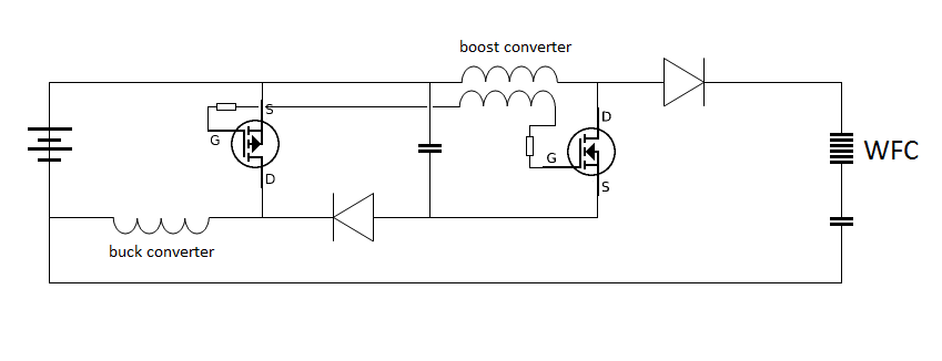
    The open ended bifilar winding ionizes the field on the pulse and collects bemf on the collapse.
    Allowing the coil to draw from the ambient.
    Thank You Mr. Tito on OU forum.


    Edit: I believe he twisted the bifilar windings, Like Bedini showed.
    Last edited by Dave45; 07-26-2014, 01:33 PM.

    Leave a comment:


  • Dave45
    replied
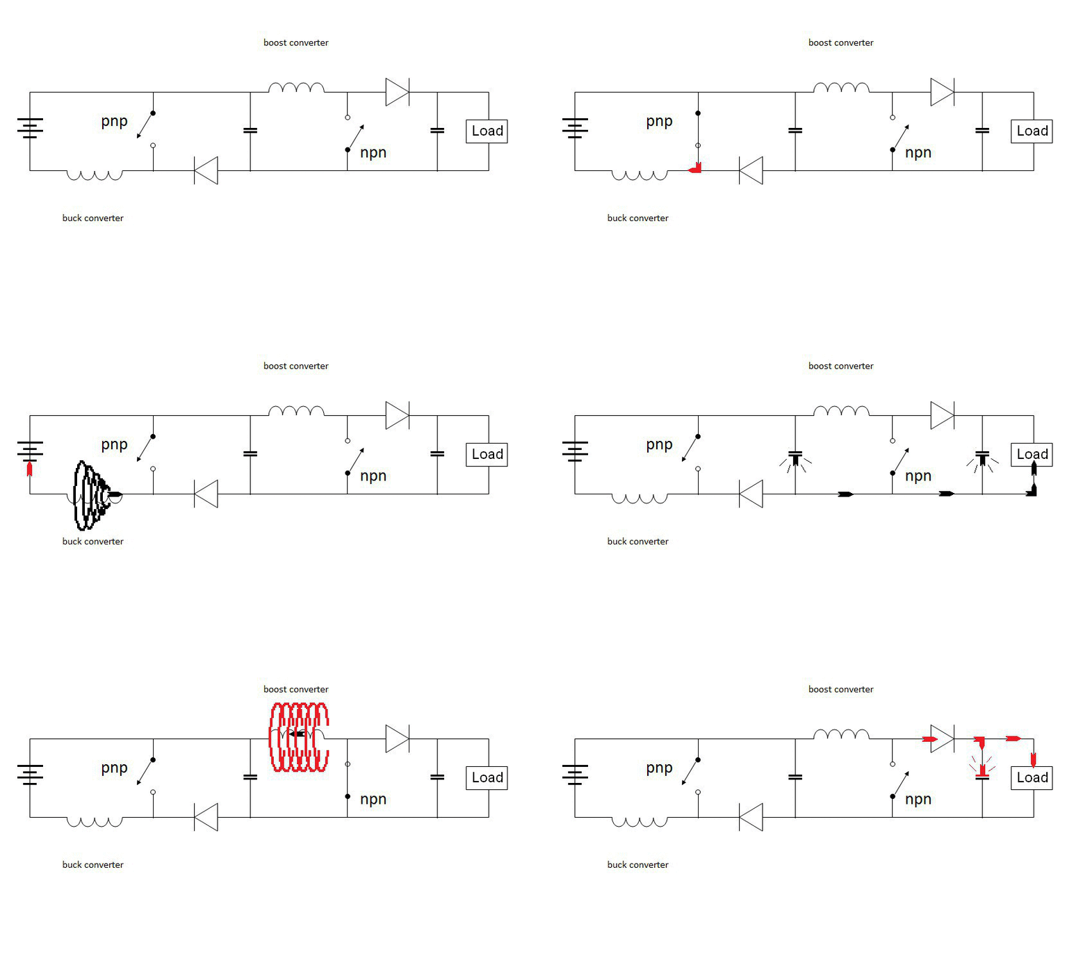
    My main purpose for making these gifs is to show the polarity reversal of the collapsing magnetic field.

    Pos pulse neg return - neg bemf

    Neg pulse pos return - pos bemf

    This indicates ionization to a certain degree is taking place.

    BIG CLUE

    Leave a comment:


  • Dave45
    replied
    DC to DC converter buck boost mode.

    Leave a comment:


  • BroMikey
    replied
    Pumpin Amps

    Originally posted by Dave45 View Post
    The logical next step was to set it up to pump amps into the WFC with limited voltage.
    I wonder what this would do to a battery.
    Hi Dave

    Exactly I wonder what it would do also. I have hooked up my sg osc to hho cells and I can't anything.

    Pretty sweet change over of the circuit dude, Kool.

    Mike

    Leave a comment:


  • Dave45
    replied
    The logical next step was to set it up to pump amps into the WFC with limited voltage.
    I wonder what this would do to a battery.

    Leave a comment:


  • BroMikey
    replied
    Circuit Giants

    Originally posted by Dave45 View Post
    Lets say the buck ran at double or even triple the frequency of the boost converter then you are dumping the cap.
    There are lots of options with this circuit, the difference with this circuit and most buck boost circuits is the separate chokes and no inverted polarity's.
    This is basically the same as Matts circuit just written up different.
    Check out complementary transistors.

    In this schem. your hitting the cell with all pos voltage.
    Greeting Dave

    You Sir are a circuit madman such a great diagram, thank you.

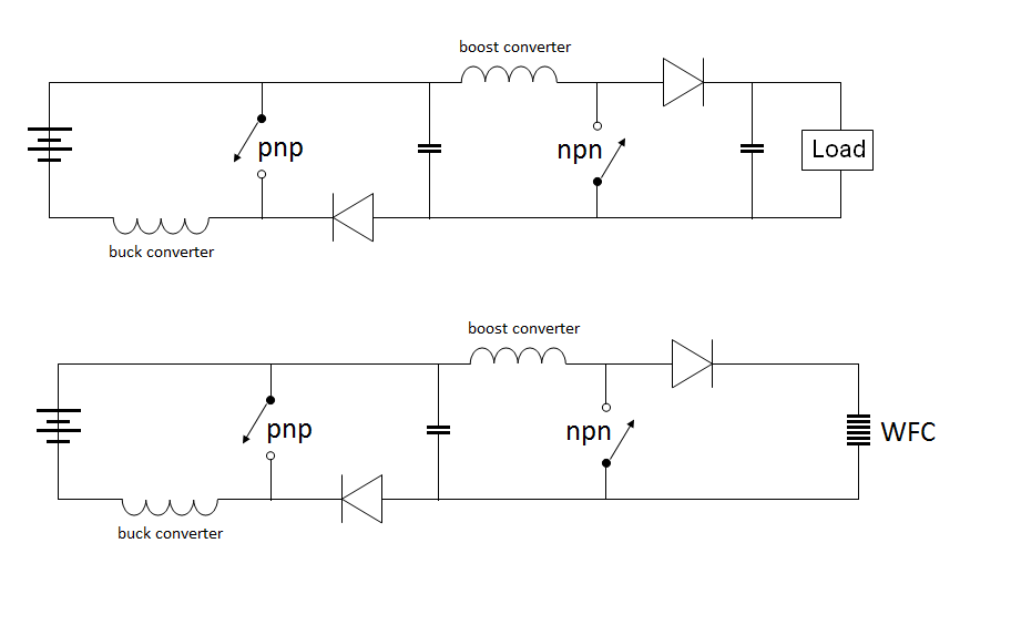
    Only a dreamer could contrive such a plan I would be happy to give this one a try in the future. I had been thinking about this all day. I remembered how I wanted to know the basics of what the standard theory behind those demos I saw and I have decided that just like the boost circuit is more efficient so might a buck boost be better?
    Well here is what I came up with. The boost circuit saves me power because I don't have to use a large resistor to slow cap charging down because the oscillation falters and sort of resets itself at every dump.

    So when the boost circuit sort a fails a buck circuit behind it might help the boost when this faltering transition comes to further increase the proper efficient handling of the momentary failed oscillation.

    I am not sure from there if I know how to explain it. I just figure if a boost saves me power and uses it more efficiently then a combination of the buck along side the boost might play a roll of it's own as well.

    I think you have a winner there Dave.

    Have you ever tried one for anything?

    Mike

    Leave a comment:


  • Dave45
    replied
    Lets say the buck ran at double or even triple the frequency of the boost converter then you are dumping the cap.
    There are lots of options with this circuit, the difference with this circuit and most buck boost circuits is the separate chokes and no inverted polarity's.
    This is basically the same as Matts circuit just written up different.
    Check out complementary transistors.

    In this schem. your hitting the cell with all pos voltage.
    Last edited by Dave45; 07-24-2014, 08:42 PM.

    Leave a comment:


  • BroMikey
    replied
    Dumping at High Frec's

    Originally posted by Dave45 View Post
    Yup I knew you were there Dave and yes I want to shoot my true series cell Hydroxy pack with the good stuff.

    In the picture you use a buck and then boost circuit Hummmm .................

    I will be stirring to think of why and what you said about using both buck and boost together and how this is more efficient. Well I did read up and watched a video of the high level Engineering demo's where this Buck/Boost idea is common now because it is known to produce higher efficiencies.

    It seems everyone knows this in the field.

    However big coils are not part of the standard approach and from here I am wondering what would be considered a decent size coil mass to start with that would make a clear distinction between US and THEM??

    Buck then Boost

    Mike

    Leave a comment:


  • Dave45
    replied

    Leave a comment:

Working...
X