This forum is preserved as a permanent archive. The community continues at eMedia Press.

Announcement

Collapse
No announcement yet.

Cap Dump Circuit

Collapse
X
 
  • Filter
  • Time
  • Show
Clear All
new posts

  • BroMikey
    replied
    Boxing It Up

    Hello friends and fellow experimenters greetings to all

    I am continuing to box up this Big Dump. One of the feats to accomplish this is making the unit self contained and not just a spiderweb of gator clips

    In the circuit look at the bottom. What you see is correct and is working fine.

    At first I was not sure and found at certain dump down cutoff resistance values that for some unbeknown reason the 555 timer firing Mosfets doubles power consumption and I felt this should be eliminated.

    I have measured the draw at around 60ma to run the 555 timer and fire the FETS. I did change the resistance for exact charging when changing timing and duty cycle.

    For instance at 3 pulses per second the timer control head circuitry draws the same 60ma to run but the amount of power being bled back from the big batteries drops to low to keep up.

    So I have a series of resistance values using gator clips to experiment for more than one setting. This will require an extra meter on board of some kind to monitor proper charging of the control head mini battery pack.

    At one pulse per second the pulses to send back to the mini pack are long with ever rising current levels during the course of that half second. I have a six resistor string that are rated at 50 ohms each at 10 watts each. This way I can switch between terminals to reset charging currents sent back to the mini pack.

    Each one of these six resistors are in series and at one pulse per second going to the 2000ah battery, I use 5 of those 50 ohm 10 watt resistors is series for a total of 250 ohms and at 3 pulses per second the resistor value changes to 100 ohms.

    This is to maintain a 100ma rise during one half of the cycle with the other half cycle falling to zero and this is an average value of around 50 ma.

    This is what I am working on so that when the power does finally go out again i will have things more and more under control being all boxed up and self contained.

    After this i will be powering the 100 ma fan rated at 120vac with 12volts.

    Then a temp sensor to shut off the control head in the event that the fan stops and the thermal runaway threatens to destroy the entire unit, that has already happened once.

    Mike
    Last edited by BroMikey; 07-24-2014, 08:03 AM.

    Leave a comment:


  • BroMikey
    replied
    Going Negative

    Okay in the picture about I installed a diode at the bottom of the circuit to trickle back a tiny bit of power to the control circuitry. This helped only slightly with the pulses still returning power to the source.

    So i will use a bridge rectifier and tiny cap and report back and change the diagram if this solves the charging of the tiny battery set.

    Using the batteries to isolate from the grid on the control head shows a good clean scope shot.

    So at present the dump has been slowed down to 1 pulse per second discharging a tiny 200 milliamp stream back to the control head. I have slowed down to charge one huge battery that was discharged to 10.5vdc for the first time. I also am using two 5ah batteries or sometimes two 7ah 12v batteries and the voltage on the batteries at rest is 12vdc after 24hrs of charging.

    So by this is can be shown that very little charge is actually going to the batteries as power is being drawn back out of them as much as is going into them.

    The single one way diode has not stopped this. I am trying to keep this all as simple as possible. I want to use something that can be easily fixed with off the shelf hardware.

    Mike
    Last edited by BroMikey; 07-22-2014, 07:30 AM.

    Leave a comment:


  • BroMikey
    replied
    Circuit Mods

    Look at the bottom again to see the added diode. I found that the two tiny batteries to run the 555 timer did charge, but each pulse went back negative taking some power back, so the diode keeps it from doing this.


    Mike

    Leave a comment:


  • BroMikey
    replied
    Chemelec

    Originally posted by Dave45 View Post
    Hey Mike some free circuits you might be interested in.
    PROJECTS
    Hey Dave

    Yes I have seen this guy since 2004. He has all kinds of starter circuits. I built my first circuit in the 1970's then in 1976 I built a preamp to modulate my CB radio.

    I use to sit in the library all summer copying circuits, back then if you copied a whole reference book the Librarian would flipped out telling you that a person can't do that. She said come back the next day to copy the rest

    I just about fell through the floor. So I kept coming back. I know circuits.

    I guess I might use a kit sometime to have some fun. This guy saves me time thanks for reminding me.

    Mike
    Last edited by BroMikey; 07-17-2014, 09:58 AM.

    Leave a comment:


  • Dave45
    replied
    Hey Mike some free circuits you might be interested in.
    PROJECTS

    Leave a comment:


  • BroMikey
    replied
    One Beginner to Another

    Greetings Fellow Cap dumpers

    I have learned something today AS A BEGINNER.

    http://flyer.thenetteam.net/images/mosfet12firing4.JPG

    I have updated the picture. Look at the bottom of the page, the very bottom.

    There you will see a bleed resistor with amp gauge using a pink wire going from the 2000ah battery set, all the way back to the run circuit for the 555 timer.

    One 300 ohm resistor sends a small amount back to the tiny run batteries (Well to run the timer). I may have to install a 27v zener if the batteries over charge.

    They are ALUM converted so I can run them at any voltage I want without damaging them. I will never use acid again from now and forever

    Have fun adding that resistor. It is a great experiment.

    Like I said in the event of another power failure (we have several per year sometimes 1 week at a shot) I am trying to eliminate all of these extra cords, plugs, extension cords running all around.

    This addition to the circuit makes for one less power adapter plugin to the Genset. At night I run batteries when the outages come.

    Before now our battery packs that we bought new failed in 2 years because I used Walmart chargers and acid batteries. The batteries would stop charging at 13.8vdc and 14vdc was hard to reach.

    I thought nothing of it at the time thinking this must be the proper voltage since we live in a space age world or very high tech. Surely a simple thing like a battery charger has to be state of the art by now right?

    Wrong!!! As it turns out 16vdc is correct for flooded cells. Or you end up with 5 percent reduction in capacity per month so after one year the battery has degraded quite a bit.

    The pulse dump circuits are the way to go!!!!!!!

    There are other ways to charge batteries but very few of these other ways have been rigorously tested and verified. GenMode could with a huge energizer or an AB class amp series pass regulator beta multiplier could do even better for all of the WIZKIDS.

    But for me just a simple added resistor and one new thing I am learning.

    Mike

    Leave a comment:


  • BroMikey
    replied
    Wave form

    Okay I was wrong about the waveform being the same when hooked to the collector side to feed the 555 timer circuit. As it turned out I worked all day burning out fets (Only 2) and learned a lot.

    I think a 5-7 watt zener say 27vdc and send that to the regulator, wel the max dump voltage is 100vdc when off and at start up.

    I will have to find my big zeners somewhere in this mess. A lot of what I have is surplus from old industrial boards and I have some new ones also.

    So what I will need to 25-30vdc at about 50 Milli-amps from a 100vdc source

    If any of you wiz-kids know the answer I am all ears.

    Making a project with wires hanging off everywhere is one thing. Boxing it up for practical use is another.

    The only one I see doing that is John Bedini because this is what he does for a living. Most experiments go to the bottom of everyone closet as spare parts. To Bad huh?

    So I am trying to keep THAT from happening AGAIN. This box needs to be self contained so when the power fails again I will not have wires running all over the room hoping the gators don't pop off

    Also if I use solar panels and my genset is off it would be nice to have the 120v fan 100ma running on battery power. This all sounds like it is no problem til you start making boards.

    I guess the fan is easier. Deciding how to power the control circuit is harder.

    I have a regulator operating now so maybe just a wall adapter and be done with it. At any rate a nice smooth supply makes for a better looking rise wave.

    The wave I got today looked like crap without using an extra 24vdc battery or lab supply.

    Mike

    Leave a comment:


  • BroMikey
    replied
    Supply Correction Problem

    Okay look at the diagram and in this picture the supply does well but if I unhook and move to the battery it is charging I get cap bank voltage (Big no no) so instead I hooked the neg lead to the collector and it now sees 25vdc I just can't figure out why it works "conducts" "THROUGH" the junction.

    It all looks good on the waveform, the same every thing so I quess I have got my little problem solved.

    See how small of a detail can stop an inexperienced guy like me? And you all thought I was a genius well on paper it looks good anyway.

    I am a beginner From now on I will have to state this almost as a disclaimer.

    Mikey
    Last edited by BroMikey; 07-12-2014, 07:59 PM.

    Leave a comment:


  • BroMikey
    replied
    Boxing up circuit

    Now that I am putting everything into one box I have removed the external power supply that is regulated and not connect to the emitter using the same 24vdc pack I am charging.

    It looks like I am going to use the 30-100vdc as a source and build a tiny buck converter to supply the timing controls.

    I tried using one of the 12vdc charger batteries but still get cap bank voltages.

    I tried a 300-500 ohm resistor of high wattage but that is the wrong way to feed my 0-36vdc regulator. isolation is very important and since I have never faced these challenges before they are a hurdle.

    It looks like I need a buck circuit to produce 20vdc to feed my triggering.

    I can't get it boxed up until I can power the timing controls.

    Mike

    Leave a comment:


  • BroMikey
    replied
    Timing Controls

    Here is an extra circuit I built last night, Well I am making two like this side by side to control timing and duty cycle.

    In the picture is the timing section. This lets me do away with the endless variable condition that exists with pots. Pots leave you wondering if you have it back in the same position as adjustments need to be made to lower input power at the end of the cycle of charge.

    This way the many switches allow for a fixed value. The next step might be to have resistors switched in and out using Zener's. At a set voltage (say 14.5vdc) the input could be slightly lowered and at the very end of the charge lowered again at 15vdc for an hour or so.

    Click image for larger version

Name:	Timing Control.JPG
Views:	1
Size:	41.7 KB
ID:	455573

    Mike

    Leave a comment:


  • Dave45
    replied
    Im in the process of moving my shop
    got my bench built, Im going to be moving my power supply's and meters today, finally.
    My next project

    Matts bipolar cap charger, Iv been studying it for a long time, Matt put the icing on the cake when he posted the schematic.
    I have some idea's to enhance the circuit--------split the aether.
    Get ready for free energy my friend.

    Leave a comment:


  • Dave45
    replied
    Im in the process of moving my shop
    got my bench built, Im going to be moving my power supply's and meters today, finally.
    My next project

    Matts bipolar cap charger, Iv been studying it for a long time, Matt put the icing on the cake when he posted the schematic.
    I have some idea's to enhance the circuit--------split the aether.
    Get ready for free energy my friend.

    Leave a comment:


  • Dave45
    replied
    You sure are quite Mike

    Leave a comment:


  • BroMikey
    replied
    Thanks

    Originally posted by Farmhand View Post
    Thanks Farmhand

    I had that one for years. Anything you wanted to point out? I am all ears.

    I guess you are saying that this is a better way to go?

    Have you done this one?

    Mike

    Leave a comment:


  • Farmhand
    replied
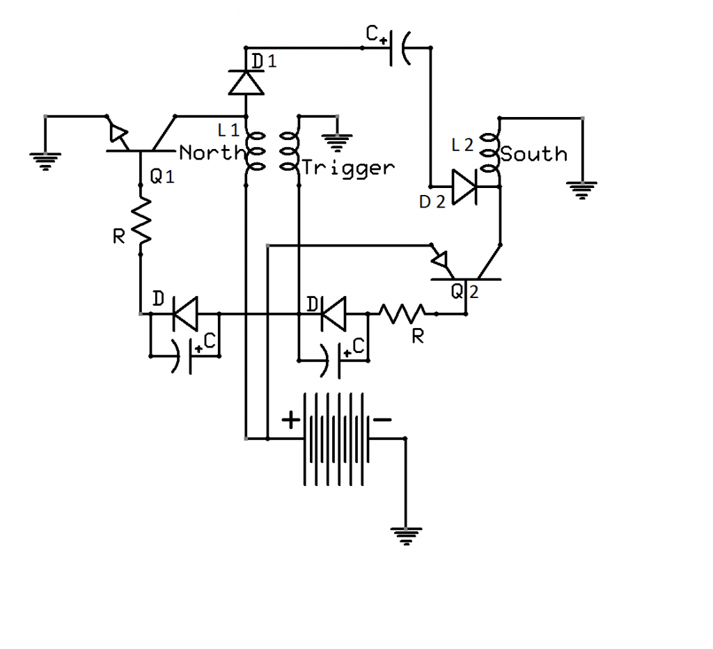
    Here you go.


    ..

    Leave a comment:

Working...
X