This forum is preserved as a permanent archive. The community continues at eMedia Press.

Announcement

Collapse
No announcement yet.

Cap Dump Circuit

Collapse
X
 
  • Filter
  • Time
  • Show
Clear All
new posts

  • BroMikey
    replied
    Thanks for speaking out.

    Originally posted by Farmhand View Post

    BroMikey, I think you are confusing power dissipation by the mosfet itself and
    the current the mosfet can pass at 500 volts.

    If we multiply 500 volts rated mosfet by 20 Amperes then that's 10,000 Watts.

    The Maximum power dissipation I think is how much thermal power the mosfet
    can "get rid of" without failing.

    The most likely reason for those mosfets to fail would improper turning fully
    "on" and holding "on" of the mosfets creating a high resistance in the switch
    for some of the current or over "pulsed" current limits. If the mosfet has to try
    to "get rid of" more than 250 Watts average then it'll struggle.

    If the mosfet turns on quickly and the resistance of the mosfet is very low very
    fast and stays very low resistance while the current flows then the mosfet
    should not get that hot.

    Another problem might be from stray inductace causing high voltage spikes
    and ringing at over the voltage rating of the mosfet.

    Basically 1 x 100 volt- 30 amp part like a IRF540N should be able to pulse a
    battery with about 30 amps as long as the peak currents are not exceeded
    and the breakdown voltage is not exceeded.

    With some protection from high voltage spikes at the mosfet drain you should
    be able to use even lower "on" resistance parts like the IRF1405.
    Rated at 169 amps continuous current and 680 Amperes pulsed current. Just
    one part with some precautions to protect it from any stray voltage spikes. Bingo.

    Note the input capacitance of this part is quite large, and would still require
    being driven well to achieve those ratings in operation.

    330 Watts maximum power dissipation and 55 volts x 169 amperes is 9295 Watts
    it can handle in switching. And it's a smaller TO220 part. Use a heat sink and
    damp the spikes at the mosfet drain.


    ..
    Hello Farmhand

    I want to thank you for pointing some of these basics out. Here is what you are saying. You just said I can take all of the 14awg copper leads on all 24 banks on my capacitors that twist up to measure the size of battery cables on your car and pass all of the current through a 16awg leg on a single transistor.

    See the way I look at it? I have a 2awg collection of terminals minimum and you want me to pass all of that from emitter to collector using one part?

    I am looking at this cap bank based on how the pathways offer resistance to the pulses.

    Strictly common sense that if you have a single transistor that has a physical leg size of 16-14awg then it does not make good sense to try to pass the current through that part coming from a conductor the size of your finger.

    I am not looking at this from a math prospective, just simple pathways.


    Please explain your reasoning here.

    Mike
    Last edited by BroMikey; 06-17-2014, 10:15 AM.

    Leave a comment:


  • Farmhand
    replied
    BroMikey, I think you are confusing power dissipation by the mosfet itself and
    the current the mosfet can pass at 500 volts.

    If we multiply 500 volts rated mosfet by 20 Amperes then that's 10,000 Watts.

    The Maximum power dissipation I think is how much thermal power the mosfet
    can "get rid of" without failing.

    The most likely reason for those mosfets to fail would improper turning fully
    "on" and holding "on" of the mosfets creating a high resistance in the switch
    for some of the current or over "pulsed" current limits. If the mosfet has to try
    to "get rid of" more than 250 Watts average then it'll struggle.

    If the mosfet turns on quickly and the resistance of the mosfet is very low very
    fast and stays very low resistance while the current flows then the mosfet
    should not get that hot.

    Another problem might be from stray inductace causing high voltage spikes
    and ringing at over the voltage rating of the mosfet.

    Basically 1 x 100 volt- 30 amp part like a IRF540N should be able to pulse a
    battery with about 30 amps as long as the peak currents are not exceeded
    and the breakdown voltage is not exceeded.

    With some protection from high voltage spikes at the mosfet drain you should
    be able to use even lower "on" resistance parts like the IRF1405.
    Rated at 169 amps continuous current and 680 Amperes pulsed current. Just
    one part with some precautions to protect it from any stray voltage spikes. Bingo.

    Note the input capacitance of this part is quite large, and would still require
    being driven well to achieve those ratings in operation.

    330 Watts maximum power dissipation and 55 volts x 169 amperes is 9295 Watts
    it can handle in switching. And it's a smaller TO220 part. Use a heat sink and
    damp the spikes at the mosfet drain.


    ..
    Last edited by Farmhand; 06-17-2014, 07:53 AM.

    Leave a comment:


  • BroMikey
    replied
    Progress report of Dump Circuit.

    I am back with an update that my transistor blew up Remember I have six of them? I am running extreme power into of surging voltages and amp fluctuation plus 100 degree heat in the room.

    No mercy, 100vdc input at 7-12 amp fluctuating on input side. 3 ohm resistor to run all of the power through to the cap bank.

    Output side 35 amp pulses 3 times per second.

    3 Days later one FET is shorted.

    Fet temps were 125 degrees for 3 days.

    Conclusion:

    (1) Six Fets are not enough to handle this much power.

    (2) Poor steering of gates produces heating

    (3) Poor steering and not enough fets? BOTH?

    When reconsidering I would have to say that each fet might be capable of 3 amps of surging high voltage. This fet is rated at 280 watt max burnout.

    SO let us say that each fet rated max 280 watts is good for 200 watts all day long 365 days 24/7.

    I have not put my thinking cap on much till things burnout.

    I am passing 35 amp pulses using 6 parallel IRFP460 FETS.

    This divided up evenly = 6 amps per FET and since each Fet is also passing voltage with it we must multiple 80vdc X 6 Amps = 480 watts in 250 mS. That is 480 watts EACH so X 6 =2800 watts.

    So we can C that my poor little darlins are smoking da junctions cause I didn't do the math

    Now like I said if I keep power levels down I can run for weeks on end with no heating and have done that but my huge battery won't charge up for days either.

    12 Fets were my goal but I just had to try it with these used FETS Used FETS? Used? Yup Used. I accidentally bought these FETS one night half asleep and didn't notice that they were used until I went back and looked at the EBAY purchase order.

    Some of you may have remembered a comment I made about broken base (gate) legs that I soldered back on. These were brittle and I couldn't figure it out.
    I had never heard of such a thing as selling fets used for the same price as new ones.

    I have the new one's now, but that really is not the point is it?

    Now I know some of you are going to jump up and say that I should be running a 40-50 percent duty and this would put me right near the line on designing for watt handling.

    I am thinking 3 amps each at 80 vdc is (240 watts) a max rating for my design not wanting to go all of the way to 280 watts and wanting even more ceiling. hum thinking.

    12 Fets maxing out at 3 amps each is 12 X 3 = 36 amp pulses

    So 12 fets will just barely do this job at Max input and output. So guess what? Gonna take away all of the excuses why it might be over heating by using the TL594 to driver TC4420 To two FETS each.

    You can use a 555 timer and a 556 dual timer or why not use a 594 well a tl594 they call it. It's a more accurate chip for higher output levels and the reason you need more accuracy at elevated power levels is that every deviation causes more friction.

    It is like trying to run the Gran Prix with a loose tie-rod end on the steering of your front wheel. At 30 miles an hour everything seems normal and at 70 MPH the front end won't shake that bad bad run it up to 250MPH and you got big trouble.

    It is time to use the math now that I have burned up most of my used FETS.

    My Fets collectively passed 35 amp pulses at 80 vdc for 2 days this is 35 X 80 = 2800 watts of power. These used FETS should handle 240 watts max so this is 3 amps each for six FETS is 18 amps collectively and is 18 X 80 = 1440 watts

    So we should all be seeing that the fets are rated at 1440 watts max handing and I am running 2800 watts through them for only 2 days.

    Mike
    Last edited by BroMikey; 06-17-2014, 05:01 AM.

    Leave a comment:


  • BroMikey
    replied
    Why?

    Why are you interested in the application of "buck boost" topology?

    Is there some way of using this idea with coils to recover energy? Or what?

    Mike

    Leave a comment:


  • Dave45
    replied

    A Half Bridge Buck Boost Converter with high side N-type MOSFET

    Leave a comment:


  • BroMikey
    replied
    Battery Voltage

    Okay update on the big batteries. The voltage has been running all night at about 11.6vdc these are ALUM batteries 880ah now converted and 1000ah.

    Now one of the batteries (As of last night) is discharging at around 11.9vdc so the conditioning is paying off.

    That would mean that to get them back down to a voltage of 11.6vdc I would have to run power all night for two nights instead of one. The voltage drop for on night is about 2 points from say 11.8 to 11.6vdc before and now 12.1 to 11.9vdc.

    Point in case: The batteries are growing in capacity.

    Mike

    Leave a comment:


  • BroMikey
    replied
    Battery size

    Notation on Batteries. These batteries were 880ah on acid, their acid trip is over I have learned that upon converting to ALUM that a rating of 880ah will go to 1000ah easily and then after some cycling will increase in capacity.
    Today marks the 4th or 5th discharge and recharge cycle for these 2 large 12vdc battery packs. When engaged at a moderate amp draw (say 35-45 amps) these batteries converted to ALUM drop to 12vdc and in an hour sit at 11.7vdc just about all night, well by morning the voltage reading might be 11.6vdc and sometimes 11.5vdc if I ran it harder the night before.

    What I am attempting to do in these descriptions or observations is to give others an idea of what to expect out of battery voltage using Alum.

    Generally the ACID battery sits 1 volt higher and is fully discharged at 12vdc.

    My ALUM batteries work good a 10vdc with not much power drop off but unless you are up for war do not discharge you big battery past 10vdc as it will take seemingly forever to get it back to 15vdc.

    With a powerful dump like I am using it is possible otherwise regular chargers would need to be employed at intervals of 12hrs on and 6hrs off using a constant current regulated supply for a long period of time to prevent internal heating and damage.

    During long power failures from natural disasters lower powered devices such as radios, TV's, fans and lights could derive their energy from large ALUM battery banks running at lower voltages without hurting the battery.

    So whatever power might be harvested from tiny windmills, water wheels or solar cells might charge the ALUM battery and effectively used which is nothing like an ACID battery that suddenly shows power and the next thing you know you are back pedaling again.

    Acid batteries sulfate greatly under a lowered voltage condition and often are lost forever unless strenuous measures are taken with endless hours of hoping and praying it revives.

    Take it to the dump Or a cap dump and blast it's door off and if it comes back to life drain the ACID and use some of that earth friendly pickle juice known as "AMMONIUM ALUMINUM SULFATE".

    Okay now the reason for popping in today. My batteries are at the beginning of cycling using pulsed power and already are taking more energy than at the beginning. Like other batteries that I have worked on the acid would charge right up and the charges would not last long either however fair for acid.

    With each cycle acid would get harder to charge but would go right up during a 12 hour period and be full soon after.

    With ALUM you must be prepared to see longer and longer charge times as the battery grows in size.

    My 100ah AGM 12vdc batteries cost $300 each and after boiling the juice out of these babies with conventional charges, in a few months they only gave me 50ah each. I have two.

    So I converted to ALUM and now after conditioning the batteries by pulse charging and discharging for 2 weeks this way they now give me as high as 170ah from each battery. They take 3x as much energy to charge and give it back so my battery is back giving me good service.

    I have 15-20 good 30ah AGM converted deep cycle batteries that "ALL" did the very same thing, giving me over 50 percent more power than rated at.

    My scooters will take the children much much further with way less problems.

    The point is that if you convert to ALUM be ready to wait long longer to get the batteries up to 15 plus volts DC.

    Right now I pulse 1 of these batteries all night then all day and discharge it at varying rates for 12 hrs. Today my other battery is not quite full so I charge them both all day together so i will still be ready tonight for discharge.

    Once in a while at this interval I stop the pulse charging because the voltages will not rise over a 6hr period for lack of ALUM plate forming especially if I have discharged the battery a little further than the last time.

    Still I will not form the plates long, either I will pulse AND trickle charge or I will stop pulsing and run at a 10-12 amp input for one hour and revert back to pulse dumping.

    There is no shame in using regular current at low levels to reform newly converted cells as both pulsed currents, continuous currents are compatible what a battery needs. It is part of a process that I have done 100's of times yet you will find no mention of this anywhere I can find on the web or any book.

    Without DIRECT CURRENT charging there would be no batteries.

    Be ready for WAR

    Mike
    Last edited by BroMikey; 06-14-2014, 08:58 PM.

    Leave a comment:


  • BroMikey
    replied
    Negative Side Discharge

    Originally posted by Dave45 View Post
    Looks like your thumpen the battery's pretty good with pos energy. I have not really studied battery's that much, maybe this is what they need.

    It would be interesting to see how they would react to a pos and neg dump.
    Hey Dave

    This thread has been great. Much input has got my hopes back up again Gotta git ready for the let down

    Now let's talk energy. I am dumping to the neg terminal and I can go to a 40 amp plus discharge of pos energy to the neg side.

    Those large batteries never get even slightly warm. I ran down one of those big beauties last night to 12.2vdc and today the discharge that they are receiving has been excepted much more readily than ever before.

    I am very excited about the way these batteries run and charge so well.

    There is no heat on these 6 devices so i am thrilled about that.

    You see the capacitor bank is the biggest that anyone has shown on the web for hitting a battery with and on top of that everyone thinks they know what I need to use for a circuit to discharge them.

    I didn't know that is for sure and like Matt said I need to learn to calculate. Well I know how to calculate and end up doing some after getting into the ball park.

    So far what I am learning "that I like the sound of" is using more capacitance to fire the gates of fets. I am looking around at the websites for stuff. Matt answered one of my questions super good.

    Matt said one thing and I said another and it went like this.

    I said I wanted to build a 12 device parallel dump with mosfets not knowing which way would be best.

    Matt said "Basically" "If I read Matt right" he said that using many drivers is the best way to cut down on heat.

    I wanted to fire 6 - 12 devices with a single driver. Of course we are not really just talking about this dump, because I want to employ these chips to drive an inverter? 2 stage?

    Yeah thats right I think 2 stage "Cheers to Matt" that last post blew me away with the circuit with 3 coils one wound ccw and the other 2 cw?

    Let me know if you build one after supper. I could do it with 2n2222 and a 2n3906 maybe or some small transistors.

    I think the cap at the top represents the cap bank?

    Anyway back to my dumping (Had to get all that off my mind first)

    The battery I am slugging is over 1000ah with a tiny little pulse of energy.

    The way I envision the process is like beating a dirty rug on a tree as the only way possible to get it the cleanest. You could sweep the rug with a broom or vacuum it but striking it with the entire weight of the rug impacting and flexing does wonders.

    This is my weak description of how much more powerful a cap dump is in cleaning and charging plates at the same time over the process of trickle charging or magnetizing plate.

    It is true that once pulse charging has been done and cycles has been accomplished that the battery does go up much faster and does not need so much force to get the job done charging. Less and less should be needed now to charge this completely desulfated battery.

    Without the Horse Power batteries are not able to be recovered in a reasonable amount of time. I have through this process of testing going on 2 years, I know what it takes.

    I have used small energizers, I have used large energizers ALL on a wide range of true deep cycle AGM converted ALUM.

    Nothing and I repeat "NOTHING" can out do a good health punch coming from the proper size unit matched to battery.

    Energizers lower resistance so a charge will be excepted and help to recover batteries then GENERATOR MODE will drive them right up.

    All energizers MUST and I repeat MUST be hooked to a cap bank first before the battery if you want to keep your battery in one piece. High voltage spikes will destroy any battery if hooked directly to an inductive spiking coil.

    Kiss it good bye. So what we learn in our practical application is that batteries WANT and NEED pos energy and POS energy is what comes out of capacitors.

    Like Matt said that he wouldn't spend so much time on the dump as he would on how I could charge CAPACITORS, hummm now I see what he means with that last circuit post.

    Get the 2x plus recovery to a cap and discharger it in the form that the battery wants "Positive pulse power"

    Today the battery went from 12.2vdc to 13vdc in an hour or so. This is the fastest I have seen it charge

    Mike

    Leave a comment:


  • Dave45
    replied
    Folks this little simple circuit Matt has shown is not something you will see everyday on the forums, not that its not known, its just not talked about.

    Study it

    Leave a comment:


  • Dave45
    replied
    Looks like your thumpen the battery's pretty good with pos energy. I have not really studied battery's that much, maybe this is what they need.

    It would be interesting to see how they would react to a pos and neg dump.

    Leave a comment:


  • BroMikey
    replied
    Video BroMikey's Dump

    Originally posted by Matthew Jones View Post
    And because of the near stress on both plates you get dielectric charging. So with a 20k uf cap rated at 100 volt it takes about 6 pulses on each coil to hit 28 -30 vdc. Each pulse (In my setup) being .4 joule input + transient spike. 20k uf cap at 30 volt is 9 joules. 12 x .4 is about 4.8 joules. So a 2x gain +-.

    Matt

    Here is my offering for the day of my 6 devices up and running.

    Capdump 6devices BroMikey Alum Batteries Only - YouTube

    Mike
    Last edited by BroMikey; 07-08-2014, 07:23 AM.

    Leave a comment:


  • Matthew Jones
    replied
    Originally posted by Dave45 View Post
    The trigger coil gives a pos pulse which activates Q1(npn) which pulses L1 with neg current, the bemf from L1 is pos it runs through D1 into the pos side of the cap.

    The trigger coil gives a neg pulse which activates Q2(pnp) which pulses L2 with pos current, the bemf from L2 is neg it runs through D2 into the neg side of the cap.

    And because of the near stress on both plates you get dielectric charging. So with a 20k uf cap rated at 100 volt it takes about 6 pulses on each coil to hit 28 -30 vdc. Each pulse (In my setup) being .4 joule input + transient spike. 20k uf cap at 30 volt is 9 joules. 12 x .4 is about 4.8 joules. So a 2x gain +-.

    Matt

    Leave a comment:


  • Dave45
    replied
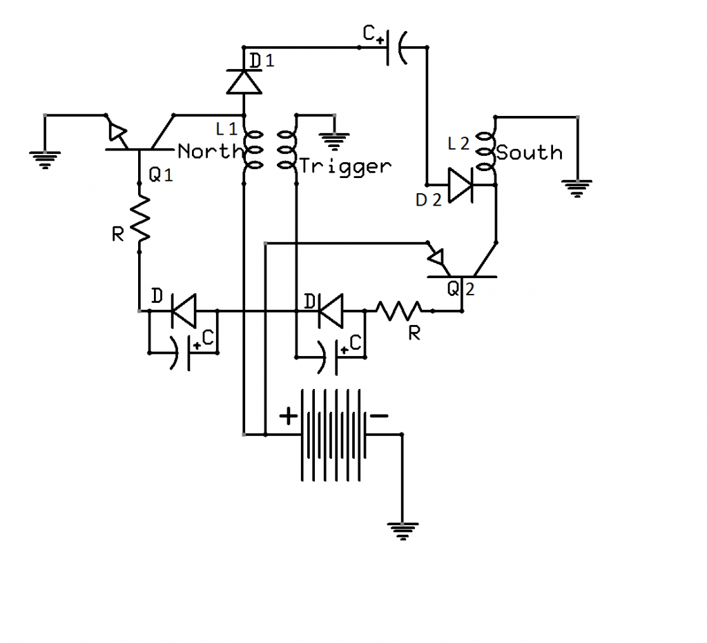
    The trigger coil gives a pos pulse which activates Q1(npn) which pulses L1 with neg current, the bemf from L1 is pos it runs through D1 into the pos side of the cap.

    The trigger coil gives a neg pulse which activates Q2(pnp) which pulses L2 with pos current, the bemf from L2 is neg it runs through D2 into the neg side of the cap.

    Last edited by Dave45; 06-12-2014, 09:39 PM.

    Leave a comment:


  • BroMikey
    replied
    Attention

    Originally posted by Matthew Jones View Post
    I wouldn't drive 12 fets with single driver. You'll get heat in some and not in others, cause they are not all going to match and you will have hard time matching them. Some will have more resistance at the gate and that will be enough to stop it from fully charging.

    Here is that circuit. Mind you its just the basics, to show you how the power flows, no specific parts.


    This will fill a cap quicker than just charging the positive side. you will need 2 separate coils one (North) wound beginning to end clockwise with the trigger winding and the other (South) wound counter clockwise. Do not take clock wise wound coil and run it backwards. This causes BEMF in the coil to reject input power and causes an imbalance. The first windings that receive power should always be closet to the iron core. Do not use a toroid or transformer body as they are designed to contain the magnetic field.

    The north coil will produce a positive spike the south coil will produce a negative spike.

    Now I understand the temptation to drive this circuit with high power. IE fets and drivers but you are not going to get the return you expect. You want large coils with as little input power as you can stand and bunch of them if you want higher results. Its just like a monopole or joule thief the point is to use as little power for as big a spike as you can get.

    This circuit if built and tuned correctly can double your available power. I have done it many times.

    I'll add a few details tonight and repost it.

    Good luck.
    Matt


    Nice diagram.

    Not to much more complex, yet it is twice as hard to see for a beginner.

    That would be me.

    I will be back with an update on my 6 fet's charging the entire bank today. Running all night and today breaking them all in.

    Those two large batteries in the basement are getting their backs beaten right now and are at about 28vdc.


    Mike
    Last edited by BroMikey; 07-08-2014, 07:22 AM.

    Leave a comment:


  • Matthew Jones
    replied
    Add that to this one.


    I forgot the caps across the diodes for quiker turn off. Bedini showed us that along time ago, really works good.

    Matt

    Leave a comment:

Working...
X