This forum is preserved as a permanent archive. The community continues at eMedia Press.

Announcement

Collapse
No announcement yet.

Cap Dump Circuit

Collapse
X
 
  • Filter
  • Time
  • Show
Clear All
new posts

  • BroMikey
    replied
    Rings

    Originally posted by Dave45 View Post
    Hey Mike
    Check out this vid, especially the iron ring, now he has 300kv 6-8 inch's apart and the iron ring stops the arcing.
    Somehow the ring will not allow ionization through its center, this barrier should separate pos and neg ions and keep them from recombining.
    Thats the problem with ions they recombine especially when the electrodes are in close proximity to each other.

    Yeah I see the ring Dave45

    Aside from the sensationalistic potty mouth tactics to gain a worldwide response we could say this guy is putting all of our fears to rest about high Voltage So much for walking around on egg shells worrying if it is going to blow.

    I see the ring and knowing about High Voltage, that size electrode should jump across from gap to gap but instead goes all the way out past the large ring first which is miles to travel.

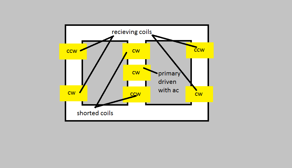
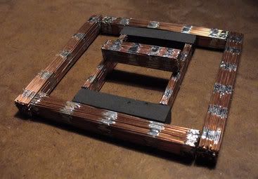
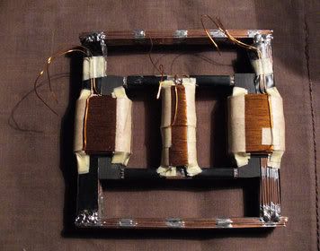
    The Bi-toroid has taught use about flux paths and that energy switched and induced into coils can be recirculated. So what we should be learning about coils is that their cores are important first in that depending on frequency of switching the heat generated represent losses.

    We all know that part. Laminate cores , ferrite, black sand, whatever til we arrive at the best core material for any given load, uh inductance, wire size, etc so switching frec's are not overloading and driving out of resonance.

    We all know that stuff. Put the coils in a nice comfortable operating range with the least amount of stress on the system, this is resonance generally.

    However looking at the Bi-Toroid we have no switching frequency with the basic system. We still have an oscillation though.

    This oscillation comes in the form of an AC sinewave at a frequency of 60 cycles per second known better by the HZ designation 60HZ.

    We all know that. So why not 120hz or 240hz and on up to see what may or may not occur? I agree, but for now we need to examine the Bi-Toroidal core arrangement. This will enable us to create more effective coil driven circuits.

    I earlier posts we see coils producing energy when magnets are attached to them because the magnets do the same thing as the Bi-Toroid lesson taught us, recirculate or redirect the FLUX PATH.

    If we recall the large ENERGIZERS John Bedini has built we see huge inductors and large weak magnets that not only trigger the transistors but if the system is bigger and the coils create enough ION Energy to surround coils out far enough things change. Also if you notice a network of large rings in the form of copper is used to collect energy. Not just electricity but the other forms of energy.

    Otherwise the Bedini Energizer Magnets if only needed for triggering would not need to be any bigger than the bike wheel designs, instead we see JOHN B. using huge beautiful double North Pole magnets costing huge somes of money to arrange, WHY??

    Flux path Engineering Boys and Girls.

    Then huge expensive magnets are cut with ceramic cutting machines at perfect angles, two of them facing other another to form and produce an altered FLUX PATH.

    We all see these rings on the larger Energizers. I wonder if the the combination of redirected energy with the spinning magnets and large copper rings are keeping the ION energy pos and neg from recombining?


    Regardless, we need to make sure that we arrange our coils so that the energy can transfer from or through one to the other so recirculation may occur.

    Energy pumping circuits are a dime a dozen yet when JOHN BEDINI does it he gets a 10X:1 COP putting 240 watts into the system and gets 2400 watts out.

    The Energizer lesson and the Bi-toroidal transformers both redirect the flux path for recirculation from one coil to the next so as to relieve the input.

    I see people using this recirculation Bi-Toroid to pulse coils with their switching circuits, also some using magnets as part of the core to redirect flux lines.

    Free standing coils that are pulsed need to be put near each other so the exchange for collecting their BEMF energies can take place.

    If the rings as are pointed out do keep the ION ENERGY separated then it may be possible to use them by placing other pulsing coils in the circuit for energy extraction and recirculation or some would say MAGNIFICATION because as RE-collections and RE-circulation takes place of the same input energy, multiples will arise.

    These are my thoughts on the subject of pulsing coils, magnetic flux paths and recombining recirculated ION energy in an effort to produce an ION TANK or reservoir of ION ENERGY.

    Once an ION TANK device is accomplished we will have an endless connection to the energy we seek. ION Energy is all around us but we are not able to keep the ION energy Component values separated as you have pointed out DAVE45 .

    Mike
    Last edited by BroMikey; 08-03-2014, 09:32 PM.

    Leave a comment:


  • Dave45
    replied
    Hey Mike
    Check out this vid, especially the iron ring, now he has 300kv 6-8 inch's apart and the iron ring stops the arcing.
    Somehow the ring will not allow ionization through its center, this barrier should separate pos and neg ions and keep them from recombining.
    Thats the problem with ions they recombine especially when the electrodes are in close proximity to each other.

    Leave a comment:


  • Dave45
    replied
    Each switch degrades the amount of power being processed in tiny amounts so the more buck-boost-boost-buck stages add to more and more losses.
    Hey Mike
    This is true there are switching losses but in an overunity situation there should be gain with each stage.
    What worries me is the coil to coil reaction, one coil would be getting hit by bemf on the opposite side, this alternate pulse will change the reactions. A coil getting hit with pos pulse will give a neg return this polarity change will load up the caps wrong. I dont really think the added stages will work because of this.
    But hey who knows
    Last edited by Dave45; 08-03-2014, 11:40 AM.

    Leave a comment:


  • BroMikey
    replied
    Energy Amplifiers


    Energy Amp homework fotos
    Mike

    Leave a comment:


  • BroMikey
    replied
    Energy Amps

    FREE ENERGY # 35 BI-TOROID TRANSFORMER - 377 % OVER UNITY MOTIONLESS - YouTube


    http://www.energeticforum.com/renewa...-platform.html

    Power Amplication

    Mike

    Leave a comment:


  • BroMikey
    replied
    Energy Amps


    Mike

    Leave a comment:


  • BroMikey
    replied
    Energy Amps


    Mike

    Leave a comment:


  • BroMikey
    replied
    Energy Amp

    ENERGY AMPLIFICATION


    Mike

    Leave a comment:


  • BroMikey
    replied
    Originally posted by Dave45 View Post
    Lets say I wanted to build a buck converter, I could hook it to a 12 volt battery and hit it with 12 volts or I could hook it to this circuit and hit it with 320 volts.
    Do you see it now.
    A boost converter increases voltage a buck converter increases amperage.
    You have to be careful how its laid out because you can get inverted voltage and inverted amperage.

    Tito Images


    Mike

    Leave a comment:


  • BroMikey
    replied
    Smaller Circuits

    Originally posted by Dave45 View Post
    The power would increase for each stage so the components power handling capability's would change.
    Fine wire on the boost and heavy on the buck, that would change in each stage as well.

    Folks the buck boost tech has been around for a long time, I just started adding it together in stages.

    Hi Dave

    I am no expert on this subject but let me share my thoughts with you so you can understand my statements about durability.

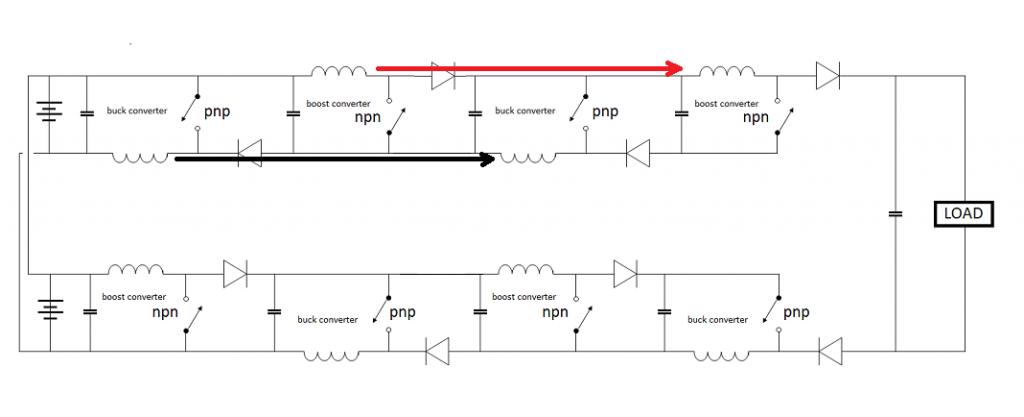
    Each switch degrades the amount of power being processed in tiny amounts so the more buck-boost-boost-buck stages add to more and more losses.

    The only reason I can see to use a cascading array is to fine tune or taylor make circuits to place into miniature devices.

    I am at a loss to understand the reasoning behind adding so many stages and what the potential benefits might be.

    99 percent power handling is a great start I agree. After we do our very best with the switching our coils won't have to work so hard to bring about a COP greater than 1? Is this the idea?

    Mike

    Leave a comment:


  • BroMikey
    replied
    Inverted power

    Originally posted by Dave45 View Post
    Lets say I wanted to build a buck converter, I could hook it to a 12 volt battery and hit it with 12 volts or I could hook it to this circuit and hit it with 320 volts.
    Do you see it now.
    A boost converter increases voltage a buck converter increases amperage.
    You have to be careful how its laid out because you can get inverted voltage and inverted amperage.

    Hi Dave just got in

    You say each stage increases power handling? One behind the other and matching stages to keep losses down because every time we put power through a switch, coil or resistor we get a power reduction from what power was first introduced.

    For instance the Microwave oven inverter boards. The object was to build a circuit to do away with the loss associated with block transformers.

    Engineering rules had stated in the past that a transformer would only pass about 70 percent and 30 percent was lost in the isolation or conversion as you prefer.

    When modern science introduced the inverter technology energy efficiencies of circuits jumped from 70 percent to 99 percent, however these conversions have been made using power transformer toroidal cores with the same efficiencies.

    So as a rule we will say that modern engineering practices only capable of designing circuit with energy coefficients of less than 99 percent.

    Inverter tech has been around a mighty long time but did not gain momentum til the 1990's when Harrison and Motorola got old and grey selling out to companies like "ON SEMI" when the new kids on the block took over.

    Most of the people on these forums were still infants at that time however the historical data is present in the record.

    Back to the Microwave ovens. Inverter boards to handle 5000 volts sent to a magnetron are not inexpensive to build, hence the block transform still prevails today with common microwave ovens. The see 10 microwave ovens a month for both commercial use and residential.

    The issue here is efficiency VS durability on the microwave ovens.

    So while all of these inverter technologies exist it appears making them practical for long term use is questionable. Longevity is may main concern building equipment.

    Applying these topologies to our coils in a completely different animal

    Mike

    Leave a comment:


  • Dave45
    replied
    Lets say I wanted to build a buck converter, I could hook it to a 12 volt battery and hit it with 12 volts or I could hook it to this circuit and hit it with 320 volts.
    Do you see it now.
    A boost converter increases voltage a buck converter increases amperage.
    You have to be careful how its laid out because you can get inverted voltage and inverted amperage.
    Last edited by Dave45; 08-02-2014, 12:55 PM.

    Leave a comment:


  • Dave45
    replied
    Folks this is an overcomplicated boost converter that puts out 320 volts, instead of taking the power out you run it into a cap and add another stage.
    Each stage increases power.
    Last edited by Dave45; 08-02-2014, 12:22 PM.

    Leave a comment:


  • Dave45
    replied
    Last edited by Dave45; 08-02-2014, 11:52 AM.

    Leave a comment:


  • Dave45
    replied
    The power would increase for each stage so the components power handling capability's would change.
    Fine wire on the boost and heavy on the buck, that would change in each stage as well.

    Folks the buck boost tech has been around for a long time, I just started adding it together in stages.

    Leave a comment:

Working...
X