

-
I guess so
Hi DaveOriginally posted by Dave45 View Post
I guess you are really to busy right now because I have no idea what you are and not building. So far I have something like close to a 50 circuits that are all mostly boost/buck design.
It is a shame that I never got an answer on the beast Osc Mod so I could try it, instead 5 other circuits have since been posted with no end in sight or any rhyme or reason.
I am lost. You are designing stuff and way past my limited abilities.
Maybe this winter you will get time, it's only a few weeks away
It's just another batch of circuit trials to run through the grinder, let me know how they come out.
MikeLeave a comment:
-
Hey Mike
Mark E and I were discussing the circuit on another forum and I ran across an unexpected reaction.
Mark seen it but I had to drudge through to find it, Im kindof hard headed I have to see it for myself to believe
Anyway Im still pluggen along been really busy with work but I will get around to building it soon but Im going to start with the basic circuit and build from there.
Leave a comment:
-
Fourth Stage?
Originally posted by Dave45 View Post
Hi Dave
If you want only the fourth power circuit limited then the resistor should go at the emitter leg of the fourth transistor but the way you have this placed, all four channels are limited by that resistor and she is going to throw some major heat.
Keep thinking it through so you can move forward with these designs. I can't do much yet so I am not going to be much help making them. Maybe in a few years I will.
So the idea as I understand it is that you want to use the resistor to toggle between switches? Why not use another small coil to trigger so that not conflicts occur?
Was that the plan? Make both switches open and close opposite each other without microprocessors?
I see your description of what you say the reason why but this is unclear to me. It is better if I ask what the goals are, such as the resistor.
Keep up the great designs. All of these circuits will need to be perfected after they hit the breadboard.
MikeLeave a comment:
-
Resistor
@DaveOriginally posted by Dave45 View Post
Yes I understand your essay of the expanding and collapsing fields however where the resistor is placed in the BEAST OSC diagram would require ALL power ALL to travel through it to the first capacitor as well as the second and battery.
I am not sure if you wanted that resistor to change the first stage operation as well as the secondary stage or stages. At present we are looking at heat build up at the resistor and this may seem small yet my circuit uses three parallel Mosfet's per a single 14awg strand of solid copper magnet wire.
Using this as boost converter at elevated power levels by comparison of the first runs I had made. The 14awg can handle 14 amps and 10-12 amps all day long without heat production.
So I will be at around 8 amps per leg on the four separate channels for a 35 amp Max ceiling @ 60vdc to charge capacitors in the bank, instead of funneling everything through this large wirewound resistor.
(.1) Ohm is suggested as a possible entry point always leaving room for tuning but I am not real sure if the PNP could handle all of that power. Of course I would need another bank of 12 Mosfet's of the PNP type to handle the power generated by the boost converter.
So this is looking more like the BEDINI energy pump without the coils and Aether gathering open ended coils. There are big differences yes but using the NPN and PNP is my focus on hardware.
MikeLast edited by BroMikey; 08-23-2014, 09:11 PM.Leave a comment:
-
Mod2

Okay this is where the resistor was suggested to be put
Matthew Wrote:
No after the second transistor. SO Positive source, NPN, Coil, NPN, Resistor, Source ground.
MattLeave a comment:
-
Just when I think I have taken the circuit as far as it will go another possibility emerges.
Leave a comment:
-
No after the second transistor. SO Positive source, NPN, Coil, NPN, Resistor, Source ground.Originally posted by Dave45 View Post
MattLeave a comment:
-
We still want to collect pos and neg bemf.
Anything you can do on the pos rail can be done on the neg rail.
Leave a comment:
-
Yes I would like to thank you also Matthew for stepping in when needed.
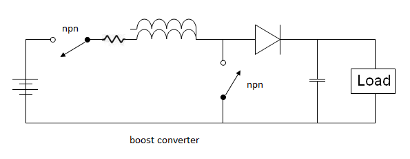
@Dave I can't always visualize the switch in place of the transistor because I need more practice doing that so i have included the Mod you made and put the resistor where I think Matthew said to put it.
Of course the notation about switch timing is awesome and that is a powerful thought.
So I am doing my best guess like this because I am use to looking at my circuit more than any other. I hope to catch up some day here it is

As you commented Dave that this resistor was added to my circuit diagram.
Thanks so much gentlemen this is one change I can wrap my head around.
MikeyLast edited by BroMikey; 08-23-2014, 07:58 AM.Leave a comment:
-
Better time that right. Make sure to turn the first NPN on First the second on second then shut the second one off then the first one. Or you'll get nothing. The resistor in the front will only cost you. Use the resistor after the second transistor. ".1 ohms" stall the current and only fills the inductor. Other wise you just make a bunch of heat.
MattLeave a comment:

 not me I chicken that reminds me every good shop needs a chicken stick



Leave a comment: