This forum is preserved as a permanent archive. The community continues at eMedia Press.

Announcement

Collapse
No announcement yet.

Cap Dump Circuit

Collapse
X
 
  • Filter
  • Time
  • Show
Clear All
new posts

  • Dave45
    replied
    What do ya think about these cores 61 Material Ferrite Rod Diameter 0 5" Length 4" | eBay their expensive.
    Also found some bobbins that are close 4set Coil Bobbin Empty Plastic Spools White | eBay
    Leave a comment:


  • Dave45
    replied
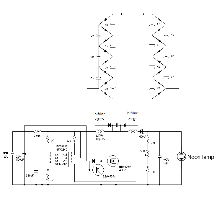
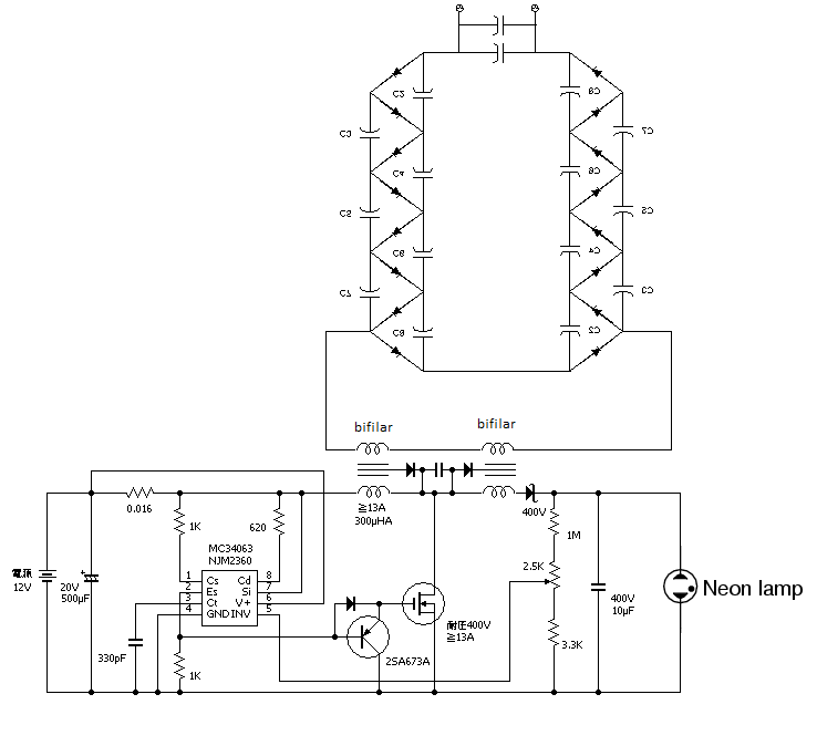
    This ladder setup could be hooked to any coil or transformer but is very dangerous.
    Its a full wave rectifier as well as an amplifier.
    Last edited by Dave45; 08-08-2014, 12:00 PM.

    Leave a comment:


  • Dave45
    replied
    The only way to control this one would be with a cap bank

    Leave a comment:


  • Dave45
    replied
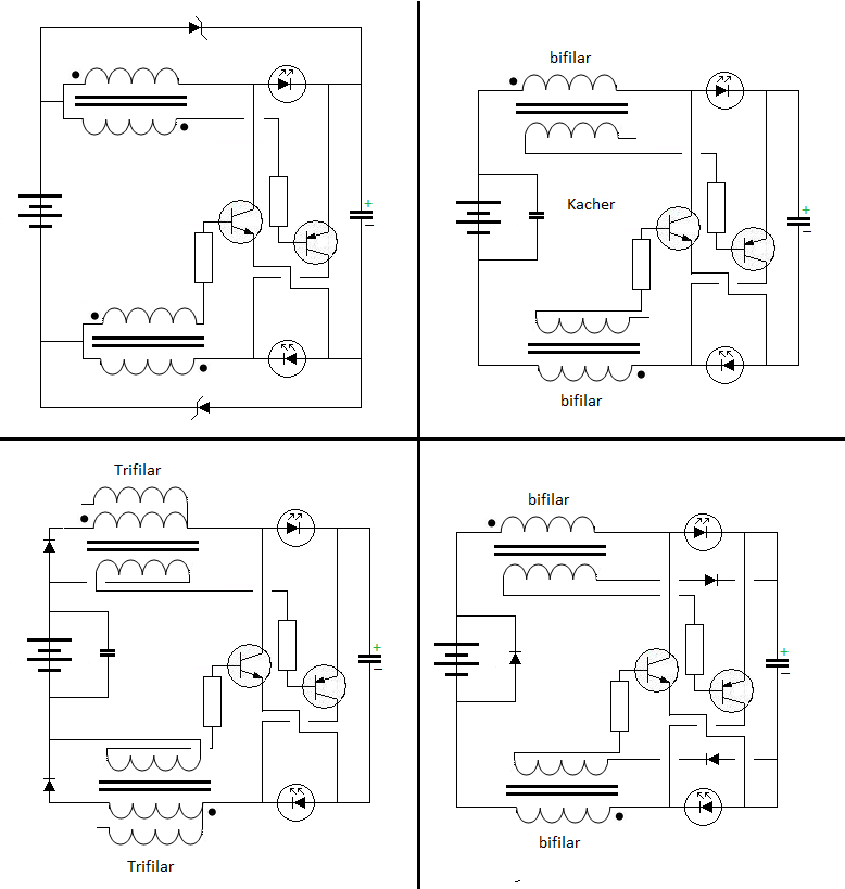
    Here's another circuit I modified, this circuit could be lethal.

    original circuit


    Modified circuit

    Leave a comment:


  • Dave45
    replied
    I believe these circuits are way over complicated, even if you found one that worked it would be very hard to understand why.

    There was another Russian guy that built one that self ran, I'll find it, anyway he said the secret was to "compare and collect" I believe he meant "separate and collect".

    In other words separate the pos and neg
    Pulse one coil with pos
    Pulse another with neg
    Which is exactly what the buck boost converter does.
    Im going to build it and build a separate ionization circuit if I have to, I dont really think I will have to using the open ended bifilar.
    Edit: I didnt mean Im going to build the sch. on this page I meant the original circuit we were working on.

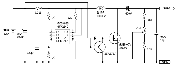
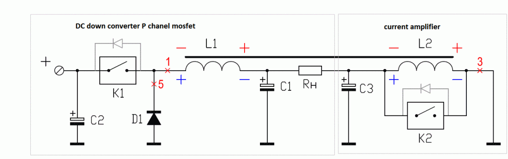
    Here's the schematic

    The DC down converter is a buck boost circuit
    Last edited by Dave45; 08-08-2014, 11:40 AM.

    Leave a comment:


  • BroMikey
    replied
    The Meek

    Originally posted by Dave45 View Post
    Yea I never wired it up, I will someday.
    Money is allways an issue but that will change soon I hope, going to order the ferrite rods and complementary transistors soon.
    I finally got my shop setup, my scopes down I need to fix it or by another one.
    I thought I was going to retire and do this full time but the Lord had other plans, raising my grandchildren their a joy but alot of work too.

    I was thinking this morning I still believe this will work and you only need one npn transistor, an ic could also be used to run the gate.
    The diode needs moved from between the coils to the outside of one of the coils.
    The diode dampens the oscillation between the two coils.
    Its Akula's 80w setup.
    Great Dave I am glad to hear that you are able to help children have a home. This shows me a meekness that others do not all possess. Meekness is quiet power meaning that all of the damage is erasable by quietly overlooking the fault. Bravo my friend indeed you are a friend.

    Now let's drift on out to circuit dream land and bring a fish in worth skinning

    I saw that guy too here he is again


    https://www.youtube.com/watch?v=e0hB3wcSxYw


    I will be back. Gonna go look this guy over. Thanks a million Dave you sure are a good helper in finding stuff.

    Mike
    Last edited by BroMikey; 08-08-2014, 10:27 AM.

    Leave a comment:


  • Dave45
    replied
    I saw your 4 rings as a bi-toroid transformer some time back and I didn't hear back on that experiment if it worked at all.
    Yea I never wired it up, I will someday.
    Money is allways an issue but that will change soon I hope, going to order the ferrite rods and complementary transistors soon.
    I finally got my shop setup, my scopes down I need to fix it or by another one.
    I thought I was going to retire and do this full time but the Lord had other plans, raising my grandchildren their a joy but alot of work too.

    I was thinking this morning I still believe this will work and you only need one npn transistor, an ic could also be used to run the gate.
    The diode needs moved from between the coils to the outside of one of the coils.
    The diode dampens the oscillation between the two coils.
    Its Akula's 80w setup.

    Leave a comment:


  • BroMikey
    replied
    Reverse winding last

    Originally posted by Dave45 View Post
    Its interesting I wonder if you could add two more cores with secondary's wound on them, well I know you could but how would it effect the power draw.

    He's using an npn trasistor so we can get an idea of whats happening with the coils, notice the orientation of the diodes on the secondary's.
    And they make alot of since it push's amperage into the secondary's on the pulse and push's voltage on the collapse.

    The primary looks to reverse its winding direction as it comes around the outside, not sure.

    It would be interesting to switch the connections and use two primary's in parallel and one secondary.

    I wonder if you used three coils in parallel as primary's with different winding ratio's could you hit a secondary with three frequency's or would it just take the path of least resistance.
    All three coils would have to be harmonically tuned to a specific frequency.
    Hi Dave

    Yes to all of your statements on windings. That is what I got also. The question about adding more rods seems like a good idea but I don't know how 3 work yet and this should be tried first. Yet when you consider the center rod winding in the same direction as the satellite rods and THAT winding doubles back over the entire set of 3 rods so as to cancel it's own field, probably more rods would pick up something.

    Like all of these baseline experiments you reach a point that not much extra is collected and I am going to assume that the breath taken finder of this pulsed coil scheme tried a few more and went back to a set of three to avoid the complex arrangement it may be evolving into.

    But for those of us learning about his finding 3 rods is best keeping the cost low and the time to set up quick.

    What he shows us like you said DAVE is the center rod as a driver of voltage and current being picked up by the (I guess in half cycle pulses) other rods but not direct coupling where input out power always degrades to less than 80 percent.

    It's worth a try like all of these thousands of experiments pasted all over the web. If I ever get set up like I want I will run about 20 of these circuits through the grinder to see what comes out.
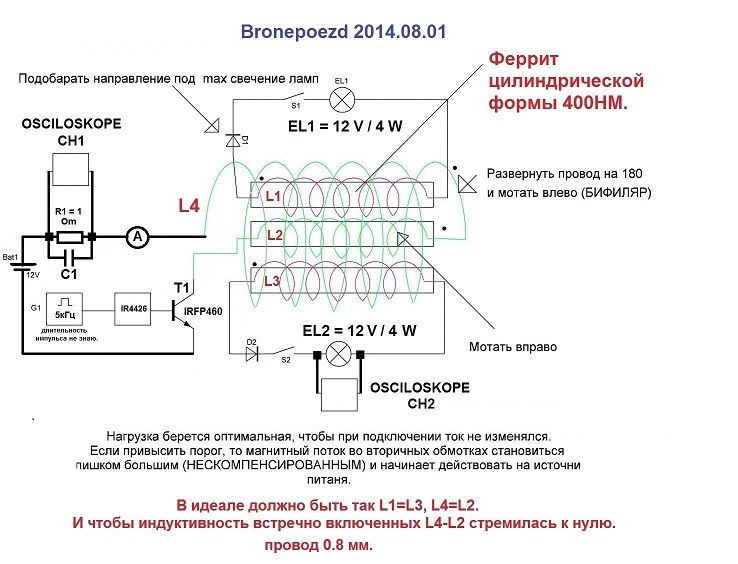
    I saw your 4 rings as a bi-toroid transformer some time back and I didn't hear back on that experiment if it worked at all.

    Mike

    Leave a comment:


  • Dave45
    replied
    Its interesting I wonder if you could add two more cores with secondary's wound on them, well I know you could but how would it effect the power draw.

    He's using an npn trasistor so we can get an idea of whats happening with the coils, notice the orientation of the diodes on the secondary's.
    And they make alot of since it push's amperage into the secondary's on the pulse and push's voltage on the collapse.

    The primary looks to reverse its winding direction as it comes around the outside, not sure.

    It would be interesting to switch the connections and use two primary's in parallel and one secondary.

    I wonder if you used three coils in parallel as primary's with different winding ratio's could you hit a secondary with three frequency's or would it just take the path of least resistance.
    All three coils would have to be harmonically tuned to a specific frequency.

    Leave a comment:


  • Dave45
    replied
    Did you see that last video of Wesley, in the Kapagen thread where he has an OU transformer using 3 ferrite rods?
    This was posted on OU forum, Im like everyone else dont know if its ou but is an interesting setup.
    I need to study the ac reactions in a coil, I got into studying the boost and buck because they were simple.

    Leave a comment:


  • BroMikey
    replied
    Circuits

    Originally posted by Dave45 View Post
    Hey Mike I agree we are working with Torsion fields
    So I started playing with the joule thief schematic,
    The last one is interesting it loads up the cap on both sides then is recycled through the switches, capacitive discharge.


    I think we all tried this one right? However with all of the circuit pictures that you can generate with your machine, I dare say that most of them have ever been tried. Did you see that last video of Wesley, in the Kapagen thread where he has an OU transformer using 3 ferrite rods?

    https://www.youtube.com/watch?v=OhJY...ature=youtu.be

    Well I think it is 3 rods? He sounds like he is saying 2 rods but the picture shows 3 rods very small. He is running 4.6 watts and claims an 8 watt output or that he is lighting two 4 watt bulbs.

    He is a teacher engineer. Wesley explains proper measuring techniques so as not to confuse input output figures.

    Like many he is lighting 2X4 watt lamps off a special tiny transformer and using only 4.6 watts but I am unsure if the bulbs are full bright and so forth.

    One very important item he talks about and shows specifically is the winding of the transformer. The direction of winding is changed once the center rod is covered and reverses direction but goes over all 3 wound rads together.


    He also points out the reason being that cancellation of self induction takes place for a net magnetic field of zero.

    Also that this is an OLD OLD practice when winding wire wound resistors so self induction is cancelled out.

    The Kapagen and other winding instructions have similarities including this one where winding can be free to produce energy without being directly coupled to the primary.

    I think the goal to finding MORE transformer designs is to make them where flux paths are not arranged in the conventional sense. So this means pulsing a coil then finding away to collect the ION field without direct coupling.

    Some use the term "LOOSE COUPLING"

    JOHN B and many others have had tiny circuits running for the last 50-100 years and we have not found their secret even with far more at our disposal.

    Mike
    Last edited by BroMikey; 08-05-2014, 08:22 PM.

    Leave a comment:


  • Dave45
    replied
    Hey Mike I agree we are working with Torsion fields
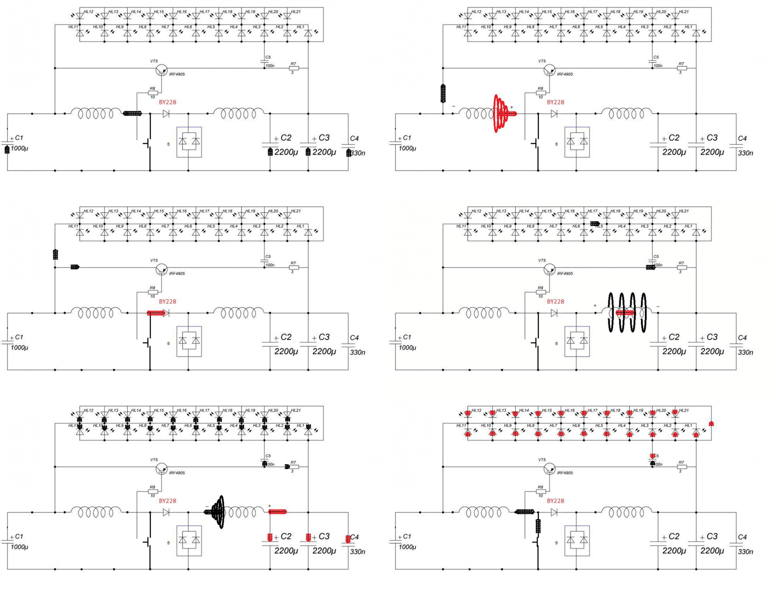
    So I started playing with the joule thief schematic,
    The last one is interesting it loads up the cap on both sides then is recycled through the switches, capacitive discharge.


    Leave a comment:


  • BroMikey
    replied
    Thinking Back

    I don't have much time right now but let me rephrase about systems that amplify energy. Not only diverting the flux path but also conflicting or slightly altered frequency harmonics that ARE in sync or in resonance can cause openings in the Aether.

    Let me say it again.

    The explanation for a 3 channel primary and one secondary like in one of the Bob B. pulse circuits goes like this. The alternator that failed lead Bob to find the answer. It wasn't pretty picture perfect resonant sync on a scope that was found to bring in the extra from who knows where.

    When these circuits are adjusted to cause turbulence a whirling tornado down through the center of the toroidal increases in size and magnitude.

    When it is picture perfect resonance on a scope ain't nuttin goin on but da rent. The key question is, what did 3 winding alternator do. And that alternator was on it's way to it's death taking a royal beating.

    The failing alternator was anything BUT in perfect resonant harmony (Give me a massive break) so the conclusion is that the replicated wave forms as seen from the failing alternator were in conflict.
    Anyone with any common sense whatsoever knows that a car alternator that the diode bank is leaking passing ac and dc causing heat can not be and picture perfect resonant wave.

    People all over the web focus of resonant waves thinking that resonance is some how the most important piece of the puzzle.

    So are we going to called it resonance when the circuits are adjusted to conflict and draw more power? Are you? Because that is how it is on these systems.

    Resonating with what? We want to resonate with the Aether and the Aether is keep everything closed up, sealed up so the Aether is on the outside of our systems. The Aether does not want us resonating with the Aether because this constitutes a break.

    The Aether is the MUMU Nature with her arms open wide to surround and keep everything the same. We want to resonate with MUM and MUM sees resonance on the inside as harmony, no conflict.

    However if we figure out how to resonate with nature don't forget the consequences of not being able to control the door once it is open you had better know what you are doing.

    Johan had a power surge so big that it fried 200 amp power line circuits all the way to the pole. This is an avalanche where an experimenter opens a door to resonate or connect with the Aether.

    We are not ready to do that as beginners. Very few can control it where the door is open slightly and can close it.

    The only thing that some of these circuits work well with are HHO cells or batteries because uncontrolled reactions with occur. Maybe a water capacitor.

    I saw Stan Deyo's talks about coils all over an aluminum craft to lift it.

    These are similar in design where the simple 3 channel generator works with water and the 6 channel up to 12 and 16 channel produce enormous amounts of energy for lifting against gravity.

    Resonating with MUM Nature is a different set of rules.

    Mike
    Last edited by BroMikey; 08-05-2014, 02:35 AM.

    Leave a comment:


  • BroMikey
    replied
    Rings

    Here are a few more rings. Don't let anybody sell that wooden nickel where a toroid core such be stayed away from. Toroidals ARE rings and may well serve a similar purpose as the other experiments WITH rings.

    Oh yeah back to the picture of the Energizer. Copper pipe it used to carry normal electrons yet the skin effect is a well known so the radiant travels on the skin and not down the center of the solid wire.

    ENERGY-RECYCLING TRANSFORMERS


    Please remember this: Notation: Please remember.

    I have the Bob Boyce hex controller. I have the toroidals WITH the wire. Remember this that radiant travels along the outer skin of the wire so my wire it silver coated.

    Silver wire is expensive but has it's place.

    Bob has related to me over the phone and in person at my house the complete operation of his invention many many times. I had Johans code at one time for charging batteries I think I have it somewhere but don't understand it..

    I know something about why it works.

    Resonance is not everything.

    In Bob's tech the alternator was failing on his boat and he got huge boosts of energy during races not knowing where from.

    His work was to find out why THAT 3 winding motor generator called an alternator could randomly kick out so much more power and Bob came up with a modified sinewave inverter alteration to start then adding 2 more frec's.

    42khz,21khz,10.7khz is a generalization.

    These 3 were made to conflict with one another intentionally to open the fabric of space. These 3 frec's were set to interact and conflict just as the car alternator did.

    All I am saying is resonance is not the whole universe. The field I am referring to is called a torsion field with a cyclonic swirling force. This is where forces are MADE BY FORCE to interrupt one an other nature will come in to repair the beach.

    Mike
    Last edited by BroMikey; 08-05-2014, 01:57 AM.

    Leave a comment:


  • BroMikey
    replied
    Rings


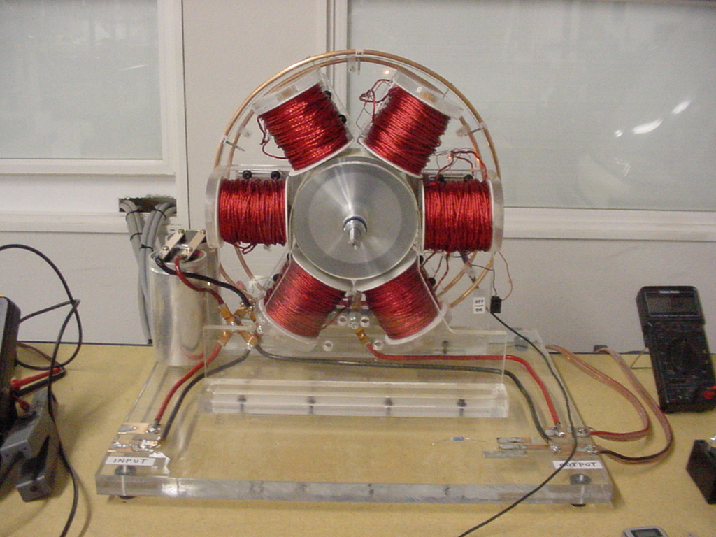
    Notice the large Ring??? In this case it is said that the ring is a collection device for IONIC transfer.

    Mike

    Leave a comment:

Working...
X