This forum is preserved as a permanent archive. The community continues at eMedia Press.
Announcement

Collapse
No announcement yet.

Cap Dump Circuit

Collapse
X
 
  • Filter
  • Time
  • Show
Clear All
new posts

  • Dave45
    replied
    Oh its on now, this would cause the coils to suck from the ambient through the open ended bifilar's.
    Last edited by Dave45; 08-22-2014, 11:41 AM.

    Leave a comment:


  • Dave45
    replied
    If you notice in the mod I made to your circuit I added a resistor to dampen the pull on the bat when the magnetic field collapses.
    I was pondering the resistor and realized a switch would be better, it breaks the connection to the power supply on collapse.

    If both switches worked at the same time it would break the connection.

    Leave a comment:


  • Dave45
    replied
    I have an idea to eliminate the diode ---- pressed for time right now will get back to ya.
    Sometimes when it hits paper it makes no sense


    Was thinking of recharging the drive battery's, one winding could be rerouted to charge the bats or any number of windings depending on energy needed.

    Leave a comment:


  • Dave45
    replied
    Your question about the diode got me thinking.
    The diode is there to control the input more than for the kickback.

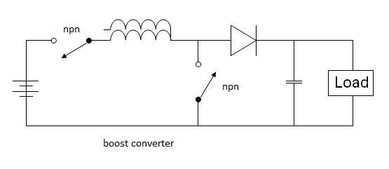
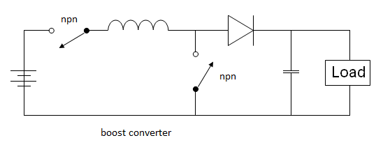
    As you can see in this boost converter animation the npn transistor delivers a neg pulse to the coil, the diode's orientation will not allow neg energy to flow into the load but does allow pos energy to hit the load.

    I have an idea to eliminate the diode ---- pressed for time right now will get back to ya.

    Leave a comment:


  • BroMikey
    replied
    Great Buck Add on

    Originally posted by Dave45 View Post
    Yea Mike its a buck converter.

    Totally awesome, I thought you were sneaking in another Kool buck circuit. Even though I am no good at designing yet I can still spot them


    Originally posted by Dave45 View Post
    Your circuit inspired me,

    She ain't my circuit but thanks 4 the pat on the back. The circuit is a JOHN BEDINI SG Osc circuit off of a patent that was modified by Laserhacker and Patrick. Bless Pat's heart he spent time showing the slow learners like me how to get off the couch with his youtube videos, couldn't have done it without him.


    Originally posted by Dave45 View Post
    I was trying to think of a way to run the first stage at a higher frequency than the second to really charge the cap for a big discharge, Your circuit came to mind, instead of changing the frequency just parallel coils in the first stage = bigger bang in the discharge, second stage

    Yeah yer my main man I am in flynn. This is the part where the standing ovation goes AND where I ask a million questions about them there coils and what they do. Seems like we'ed bee filling up those coils like filling up a tank of water. Then send it all to the cap bank. still I gotta think it over a bunch more so I can make up my mind what to do.

    Like said coils would raise the voltage say 5000 turns of number 10awg? Naw that can't be right maybe 25 turns hummm... I don't know where start.


    Originally posted by Dave45 View Post
    The coil, its a directional coil,

    Bi-directional coil? humm does that mean no diode? I think it means no diode forcing the power in only one direction, no?


    Originally posted by Dave45 View Post
    can be wound cw or ccw, easy to add layers or remove layers for tuning, lower resistance = faster rise and fall time, quick response.

    Your energizer circuit is a suped up boost converter your hitting the battery's with high pos energy, the mod allows you to hit the bats with a high neg pulse.

    Humm sounds like I need to start with 500 turns and start backwards but I don't know. Bedini's patent shows about 30-40 feet for his tube oscillator coil.


    Originally posted by Dave45 View Post
    Is this what the bat needs? dont really know.

    Well now that is a very important question to ask. Options my main man options. You see if I go directly to the battery I only use mode one which is the normal SG OSC. This mode is the very first circuit that I have posted of the Solid State School Girl oscillator. This provides voltage spikes of radiant energy that if left unattended will smash the battery plates into pieces.

    That brings us to GENERATOR MODE as posted where the coils boost but deliver current pulses to the battery, THAT IS WHAT A BATTERY NEEDS.

    Great question. Next we need to take a look at some other ways of operating the SSSG boost converter.

    If we stay in mode one or voltage spiking mode that ruins batteries in the long run, we can instead sent the voltage to a capacitor bank and this radiant spike is said to teach the capacitors to charge themselves.

    Or we could say this in another way, we could say that the capacitor voltages climb right up even after they are disconnected from the power.

    We could also say that radiant pulses in the form of spikes filling up capacitors
    will re-gauge the energy and protect the battery. Also the conditioning of capacitors using radiant is good for capacitors.

    The capacitors are said to charge quicker after being conditioned with the spike so you can see where we are going here. We want options my number one man options.

    So what should we say then about GENERATOR MODE? That is warm current pulses, okay? Well let's say this, after the conditioning of the battery or the capacitor bank GENMODE is turned on.

    This Genmode drives up capacitors with warm current pulses even faster for only a small amount more input power.

    The entire procedure above is followed off and on depending on the state of the capacitors or the state/condition of the battery.

    What we SHOULD do in the end is replace the battery and the capacitor bank with a good sized SUPERCAP and do a looper winding to get a continuously running circuit that keeps getting higher voltage on the cap.

    Lasersaber has done that with an LED getting his circuit to run for half an hour using only a 50ua drain from the capacitor while running 1 or 2 LEDS full bright.


    Originally posted by Dave45 View Post
    Tesla was into discharging capacitors into a coil and thats essentially what we are doing in the second stage.

    The key to free energy lies in the working principle of the buck and boost converter.
    Hit a coil with pos pulse and get a neg kickback
    = collection of aether
    Hit a coil with neg pulse and get a pos kickback

    Ion generators collect pos ions around the neg electrode and neg ions around the pos electrode = separation of aether into its pos and neg polarity's, ready for collection.
    humm.. what can I say that is a lot of good stuff to ponder Dave thanks A Million.

    Mike
    Last edited by BroMikey; 08-21-2014, 05:30 AM.

    Leave a comment:


  • Dave45
    replied
    Yea Mike its a buck converter.
    Your circuit inspired me, I was trying to think of a way to run the first stage at a higher frequency than the second to really charge the cap for a big discharge, Your circuit came to mind, instead of changing the frequency just parallel coils in the first stage = bigger bang in the discharge, second stage

    The coil, its a directional coil, can be wound cw or ccw, easy to add layers or remove layers for tuning, lower resistance = faster rise and fall time, quick response.

    Your energizer circuit is a suped up boost converter your hitting the battery's with high pos energy, the mod allows you to hit the bats with a high neg pulse. Is this what the bat needs? dont really know.

    Tesla was into discharging capacitors into a coil and thats essentially what we are doing in the second stage.

    The key to free energy lies in the working principle of the buck and boost converter.
    Hit a coil with pos pulse and get a neg kickback
    = collection of aether
    Hit a coil with neg pulse and get a pos kickback

    Ion generators collect pos ions around the neg electrode and neg ions around the pos electrode = separation of aether into its pos and neg polarity's, ready for collection.

    Leave a comment:


  • BroMikey
    replied
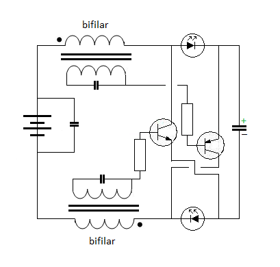
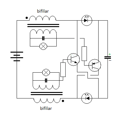
    Generator Mode

    This is how I connect my energizers most of the time even with a cap dump pumping up capacitors is much faster for only a small amount more power.


    Sometimes I think if I had a big enough energizer mode one might charge cap faster than Genmode does. All I know is Gen Mode is hooked up the same as a joule thief and my new setup is using 3 transistors for each of the four power coils at 14awg.

    Mike

    Leave a comment:


  • BroMikey
    replied
    Parallel Wound Coil???

    Originally posted by Dave45 View Post
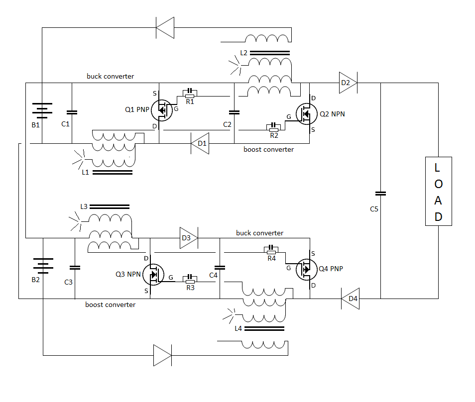
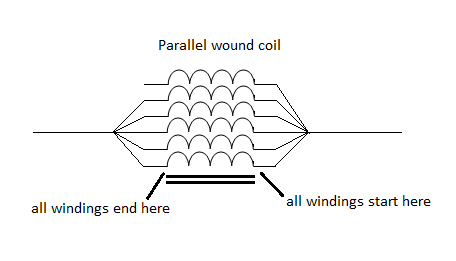
    The pnp switches would need to be paralleled to accommodate the amount of power being dumped.
    A heavy winding 10 guage
    A paralleled wound coil
    Oh I see. This is something new for me, I never would have guessed any of this. Okay let's start again, you posted my energizer and added a special dump circuit, gotcha. I missed what you were doing at first and now I am still not so sure what that might do. hum... very interesting my main man very interesting.

    Can it be put to animation?

    you see in the past I used a neg dump and now you are using pos, right?

    Wait I am not sure what end is up here you got me there.

    What does that new add-on do actually? Is that a pos dump or both?

    Thanks Dave for blowing my beany copter off , this stuff really fries my brain lovin it.

    I see a half bridge there and normally I use a full bridge

    It kind of reminds me of a push pull circuit I seen somewhere.

    This is the berries I got to ponder this one. Is that a buck converter?

    Mike
    Last edited by BroMikey; 08-20-2014, 08:31 AM.

    Leave a comment:


  • Dave45
    replied
    The pnp switches would need to be paralleled to accommodate the amount of power being dumped.
    A heavy winding 10 guage
    A paralleled wound coil

    Leave a comment:


  • BroMikey
    replied
    Great Work Dave

    Originally posted by Dave45 View Post
    Mike I modded your cap dump circuit
    Hope you dont mind.

    Hello Dave

    No I don't mind, are you kidding? I am glad to see ANY possible addition to my circuit. Do you think the extra loose unconnected winding might pull in some Aether at a 9khz pulse rate?

    Also what are your thoughts on wire length or coil diameter, core materials?

    I was thinking of adding a coil at the end but thought it might rise the voltage up.

    Mike

    Leave a comment:


  • Dave45
    replied
    Mike I modded your cap dump circuit
    Hope you dont mind.
    Last edited by Dave45; 08-19-2014, 02:23 PM.

    Leave a comment:


  • Dave45
    replied
    Rethinking the circuit

    Leave a comment:


  • Dave45
    replied
    Lots of work to do when the parts get here

    Leave a comment:


  • Dave45
    replied
    How would the gates react using a tank circuit on the feedback coil.

    Leave a comment:


  • Dave45
    replied
    Ordered four cores and a set of bobbins
    Will order transistors and wire next week.
    Little by little

    Leave a comment:

Working...
X