Announcement

Collapse
No announcement yet.

Eric Dollard

Collapse
This is a sticky topic.
X
X
 
  • Filter
  • Time
  • Show
Clear All
new posts

  • orgonaut314 telluric output

    orgonaut314 hi astronod here .

    ok on ya ballun always good to learn RF technics .

    what ya can try is make 2 LED` s in antiparallel and hook it up between the down output and the ground plane start with signal gen power only .
    search resonance gound plane is free floating no extra connection to ground.
    if that work , replace the the 2 led` s with a small light buld like for the bike light or smaller . if you have no small light bulbs more leds antiparallel is ok to .
    so it can hold about your 2 watts .
    you can try to with just 2 leds and the 2 watts just gently put more use out of the signal gen .

    the neon .. put it on a non conductivce stick and hold it to the top coil output .

    one lead of the neon could hit the output of the top coil .

    see what happen .

    all the best PD7Z
    Last edited by AstroNod; 05-08-2014, 04:06 PM.

    Comment


    • About copper weight.

      Hello Eric and everyone

      I've been through the three threads, and start building something based on Eric's design. Thanks Eric, nobody have ever led so many people to the real world of real science. I hope I didn't miss some parts of the discussion, but I have a question stuck in my mind. As Eric said, the copper weight in the primary condenser, the primary, the secondary, and the extra coil should all be the same, and it's a important rule which should not be violated. My question is why it's so important? I know it is the rule but I just don't know the engineering explanation. I hope it's haven't been answered before, if it did is, please somebody point me in which thread and which post it is?

      And Eric, thank you again, and thanks everybody else too.

      Ming

      Comment


      • Skin Effect

        Hi mo19841116 / ming .

        Active matter in the prim. coil must be about the same as in the sec. coil .
        However due to High frequency there is skin effect .
        So you can take area of your material , basic math. of wire its circle area and the length of the wire . for strap just count the sides and times the length .

        in the time of tesla there was no skin effect in the text books due to the low frequency skin effect is deeper than HF like MW band or HF bands .
        tesla use <100KHz . (VLF)

        the capacitor tune in the prim coil you can count the area with the prim. coil if you have a plate or vacuum cap . with small mica caps you can leave the `extra` area out . . or just leave the tune cap extra area out .

        there many online calulators who can help disign the right coils .

        however this topic skin effect i already mention in my postings before .

        due to the skin effect at >1MHz is small and smaller on higher freq. you can just take area of the material but if you want to do it perfect what you wont measure ..... you should count the depth into the material as well .
        this take much more complex calculations .

        I hope this helps ... donate some time to you

        all the best .

        de PD7Z
        Last edited by AstroNod; 05-09-2014, 08:34 AM.

        Comment


        • Originally posted by mo19841116 View Post
          Hello Eric and everyone

          I've been through the three threads, and start building something based on Eric's design. Thanks Eric, nobody have ever led so many people to the real world of real science. I hope I didn't miss some parts of the discussion, but I have a question stuck in my mind. As Eric said, the copper weight in the primary condenser, the primary, the secondary, and the extra coil should all be the same, and it's a important rule which should not be violated. My question is why it's so important? I know it is the rule but I just don't know the engineering explanation. I hope it's haven't been answered before, if it did is, please somebody point me in which thread and which post it is?

          And Eric, thank you again, and thanks everybody else too.

          Ming
          These coils are about the energy in the dielectric next to the electromagnetic wave.
          It seems there is a connection between this dielectric energy and gravitation. If that speculation is right than the mass is something to concentrate the dielectric energy in the same space between primary and secondary coil. Making one bigger would be something like making the primary coil have a bigger diameter and a lot of magnetic energy goes wasted.

          I am only speculating here.

          But equal mass on same material means equal volume. The skin effect makes it equal surface. So only the mass that carries a current is taken into account.

          On the other hand it might be just to make the two coils have the same capacity? But than the rule that the capacitor and the inductor in the primary would have to be the same volume does not make sense to me.
          Last edited by orgonaut314; 05-09-2014, 09:42 AM.

          Comment


          • There is a strange thing with my Tesla coil now.

            For instance I put the driver on this morning and there is a hell of a radiation coming from the coil. On the driver side of the balun I measure 13,2V and 100mA. That makes 1,3 Watt. I had to tune the input down to keep the radiation meter in a normal scale. It is maximum now.

            However the resonance has shifted to 3,69 MHz.

            Yesterday it was 3,2 MHz and I had 750 miliWatt on the driver with a much higher input voltage. So it was radiating much less than and the frequency was 3,2MHz.

            Now I know that after some time the radiation will drop again to the normal intensity at the normal frequency that is called normal because that was the resonance with the sinus generator only.

            So I have to conclude that the coil is suddenly resonating very intense at a higher frequency. Any one have an explanation?

            Comment


            • LOL I just figured out what causes the radiation to drop it was opening and closing the door! My earth wire is going through the door and somehow the door makes for extra capacitance in the ground wire (turned out to be a bad connection to ground). Leaving the door open is best.
              The next thing is that there seem to be two resonances all the time. Have to figure that one out now.
              Last edited by orgonaut314; 05-09-2014, 01:21 PM.

              Comment


              • Ok there are definitely two resonances. One was between the primary and the balun and its radiation was low to the ground at 3,7 MHz. The other was the very sharp peak at 3,2MHz that came from the top of the Tesla coil.

                I now have some 600 mili Watt into that resonance.

                Comment


                • Thank you

                  I want to send a big thank you out to "Frideric". He sent me a very generous donation and it will definitely help see this project realized to completion. Thank you so much.

                  Also I want to thank everyone who has donated to the campaign so far, however big or small. It is very nice of you all to donate your hard earned money. It is very gracious of you all to help move this project forward. All I can say is i am extremely grateful, I assure you your money will be put to good use! Thank you so much.

                  John Polakowski
                  Please help support my indiegogo campaign: Cosmic Induction Generator

                  Comment


                  • Steven Mark TPU

                    Steven Mark TPU:
                    Aaron,
                    Most of what Eric has to offer is very interesting, exciting and a challenge but does not give us 'Energy Synthesis' where we are able to power our own homes.

                    Do you have any idea where Steven Mark is these days as his system and his device have gone to ground?
                    Have chosen the TPU as the best possible means to gain this energy and studying up on its organisation as it is the best for all to build as it is motionless and just a good combination of coils and electronics that anyone can build with some kind of a profound electronics background that might include Vacuum Tubes.
                    Any assistance in this area would be greatly appreciated.
                    Steven was most disappointed by some individuals on Forums that simply failed to comprehend or follow the advice he was giving and in the end, shied away from that medium as so too does Eric.

                    Is it at all possible that the CIG (Cosmic Induction Generator) will lead to an eventual 'Energy Synthesis' device in the near future?

                    What this device actually does for those not yet up the curve, is to generate your own Cosmos and within this medium you can negotiate your own energy delivering system.
                    The comprehension of two opposing forces in natural balance is the answer to a platform for energy extraction and that is what I see the CIG being as such.
                    We are no longer dealing with a thing called 'electricity' and that is what we need to establish in our minds is that what we call classical or artificial electricity, no longer applies.
                    Thanks.

                    Smokey

                    Comment


                    • Originally posted by AstroNod View Post
                      Hi mo19841116 / ming .

                      Active matter in the prim. coil must be about the same as in the sec. coil .
                      However due to High frequency there is skin effect .
                      So you can take area of your material , basic math. of wire its circle area and the length of the wire . for strap just count the sides and times the length .

                      in the time of tesla there was no skin effect in the text books due to the low frequency skin effect is deeper than HF like MW band or HF bands .
                      tesla use <100KHz . (VLF)

                      the capacitor tune in the prim coil you can count the area with the prim. coil if you have a plate or vacuum cap . with small mica caps you can leave the `extra` area out . . or just leave the tune cap extra area out .

                      there many online calulators who can help disign the right coils .

                      however this topic skin effect i already mention in my postings before .

                      due to the skin effect at >1MHz is small and smaller on higher freq. you can just take area of the material but if you want to do it perfect what you wont measure ..... you should count the depth into the material as well .
                      this take much more complex calculations .

                      I hope this helps ... donate some time to you

                      all the best .

                      de PD7Z
                      Thanks AstroNod and orgonaut314
                      I'm following the steps to build the TMT. There is a question that confused me. First we choose a frequency and caculate a wire length with Eric's formula, then have a luminal velocity and frequency caculated with the speed of light and this wire length. And then we have a velocity and frequency in free space caculated with this wire length by Eric's formula. Then we actually measure the actual velocity and frequency. There are three pairs of velocity and frequency. My question is, is this caculated wire length for the chosen frequency a "must be", or just a initial guide? What is the difference if I just cut some wire and make the measured frequency equal to the designed frequency, or I still have to put some ring capacitor to avoid cutting the wire ?

                      Is it that, the ring capacitor is just for experimental usage, and in actual working model, we only use the actual velocity and frequency and the luminal and free space pairs just for analysis? Becaue I didn't see Tesla's design have any adjustable capacitor at the end of the secondary, and the secondary and the extra coil are actually in directly joint, both in CSN and the patant diagram.

                      Thanks again

                      Ming

                      Comment


                      • Originally posted by mo19841116 View Post
                        Thanks AstroNod and orgonaut314
                        I'm following the steps to build the TMT. There is a question that confused me. First we choose a frequency and caculate a wire length with Eric's formula, then have a luminal velocity and frequency caculated with the speed of light and this wire length. And then we have a velocity and frequency in free space caculated with this wire length by Eric's formula. Then we actually measure the actual velocity and frequency. There are three pairs of velocity and frequency. My question is, is this caculated wire length for the chosen frequency a "must be", or just a initial guide? What is the difference if I just cut some wire and make the measured frequency equal to the designed frequency, or I still have to put some ring capacitor to avoid cutting the wire ?

                        Is it that, the ring capacitor is just for experimental usage, and in actual working model, we only use the actual velocity and frequency and the luminal and free space pairs just for analysis? Becaue I didn't see Tesla's design have any adjustable capacitor at the end of the secondary, and the secondary and the extra coil are actually in directly joint, both in CSN and the patant diagram.

                        Thanks again

                        Ming
                        Originally posted by T-rex
                        There should not be much left unanswered, it is all in the "Theory of Wireless Power" and "Impulses, Waves and Discharges." But all of this pre-supposes a working knowledge of radio frequency lines and antennae.

                        Velocity depends on aspect ratio. If Secondary ratio is 18%, velocity is luminal, this only at 18%. So make the coil 20% and the velocity is a bit faster than luminal. The reason, to compensate for the slowing caused by insulation.

                        The secondary is coupled to other coils and capacitance. This lowers the velocity greatly. Thus to compensate the coil wire is shortened by 2/pi=0.63662=63.7% to bring the frequency back up to the proper value.

                        As for the extra coil; for a coil aspect ratio of 100% the coil effective velocity is 187% that of luminal velocity (along the coil wire). This coil is burdened down by insulation and gradient rings as well as what little coupling Exists. Thus the coil Wire is lengthened to 157% velocity factor. This is to say, rather than calculating the extra coil on a velocity of 187% that of light along the coil wire to figure the quarter wave, we now instead, in order to compensate for the burden, use a velocity of 157% that of light along the coil wire to figure quarter wave. 157% is equal to pi/2.

                        Therefore, secondary 2/pi, extra coil pi/2.

                        (Longer Extra)/(Shorter Sec.) = (pi/2)/(2/pi)=pi^2/4=2.465

                        Where pi is a correction factor, not an intrinsic mathematical relation. But it may be that by using pi some "magic" resonance may take form. (Experiment and see).

                        Also important in the use of gradient rings at coil ends. These are like capacitors and keep losses low by not stressing insulation with flux concentrations. Quarter inch copper tubing fine. It must be slotted so as not to be a shorted turn! Connect end wire of coil to ring, it is a final turn.
                        A tuning condenser will also have the effect of increasing the selectivity/reducing the frequency response of the coil. When the coil is "free" it responds to a much wider frequency band than if it's tuned down to a certain frequency.

                        Also there are some differences between Eric's design and the CS coil.

                        As for the condenser in that case, this (slightly modified) diagram is from CS Notes. Although in the text Tesla states that as he has it it doesn't affect the frequency much. But at the same time a scale model in "free" resonance has a much higher measured propagation velocity than the CS coil due to the stray inductance and capacitance. So if matching that is the goal then it still has to be tuned down.

                        http://www.teslascientific.com/

                        "Knowledge is cosmic. It does not evolve or unfold in man. Man unfolds to an awareness of it. He gradually discovers it." - Walter Russell

                        "Once men died for Truth, but now Truth dies at the hands of men." - Manly P. Hall

                        Comment


                        • JP's CIG Fundraiser

                          Originally posted by jpolakow View Post
                          Also I want to thank everyone who has donated to the campaign so far, however big or small. It is very nice of you all to donate your hard earned money. It is very gracious of you all to help move this project forward. All I can say is i am extremely grateful, I assure you your money will be put to good use! Thank you so much.

                          John Polakowski
                          I’ve been on vacation and away from a keyboard for the past week or so.

                          @JP - Nice job with your introduction and fundraising campaign for the CIG project. Albeit via the internet, it’s nice to finally meet you JP! - To put a face and voice behind the typing of words. Also your website JohnPolakowkskiScience.com is great.

                          Impressive is the attention to detail regarding 1KW transmitter, for instance the crafted housings for the 829b tubes including fans look great and are certainly ideal for the task.

                          I’m yet to throw some coins into the hat but will do so soon. I can’t quite afford to contribute as much coin as I would like to, however I’ll also be forwarding the campaign through the networks here, which hopefully might add a few more $. – Good luck with it all.

                          I’ll be aggressively building again and hope to have some further progress to share soon. My TMT/CIG (Receiver or other half of the CIG nears completion and testing will soon begin). Also working on “what makes the best reflector” or terminal capacitance, in order to optimise the terminal reflection and thus the telluric output. (Although for the CIG the opposite may be best). Secondary coils only at this stage. - Also some videos have been, made just have to upload them when there is time.


                          @All: Good to see others having a crack at this too, particularly the newer people like Astronod, & mo19841116 (Ming). @Astronod, - I wrote you a reply recently regarding your work and some of your videos, but I’ve lost/misplaced the file before I was able to post it. – Maybe I’ll find it. - How’s the burnt finger now? Ouch, - It can bite!

                          Sputins
                          "Doesn't matter how many times you kick the coyote in the head, it's still gonna eat chickens". - EPD

                          Comment


                          • Originally posted by dR-Green View Post
                            A tuning condenser will also have the effect of increasing the selectivity/reducing the frequency response of the coil. When the coil is "free" it responds to a much wider frequency band than if it's tuned down to a certain frequency.

                            Also there are some differences between Eric's design and the CS coil.

                            As for the condenser in that case, this (slightly modified) diagram is from CS Notes. Although in the text Tesla states that as he has it it doesn't affect the frequency much. But at the same time a scale model in "free" resonance has a much higher measured propagation velocity than the CS coil due to the stray inductance and capacitance. So if matching that is the goal then it still has to be tuned down.

                            Thank you dR-Green, your reply has wiped out all my confusion except one. When I done building the coils and actually measure them, I found they are somehow not at the same frequency. Like the designed frequency is 3.5Mhz, then the secondary is at 3.6-3.7, and extra coil is at 3.4, we can adjust the ring capacitor to make the secondary back to 3.5Mhz, but adding a top to extra coil will drag the frequency even more. At this stage, what should we do? Certainly we should do something to the extra coil, but how? To cut some wire and enlarge the turn-to-turn space? Or some other methods?

                            And as we go further, just assuming the secondary and extra coil are all perfect and resonate sharp and nice, now we need add a primary capacitor to the primary loop. When I make the primary LC circuit resonate at 3.5Mhz as former stated and put them in place with the secondary, I found the secondary and extra coil's frequency will always split into two. And the higher the coefficient of coupling, the larger the gap of this two frequency. What we do now? What will the frequency of the power supply be in real wireless transmission?

                            Thanks again

                            Ming

                            Comment


                            • Originally posted by mo19841116 View Post
                              Thank you dR-Green, your reply has wiped out all my confusion except one. When I done building the coils and actually measure them, I found they are somehow not at the same frequency. Like the designed frequency is 3.5Mhz, then the secondary is at 3.6-3.7, and extra coil is at 3.4, we can adjust the ring capacitor to make the secondary back to 3.5Mhz, but adding a top to extra coil will drag the frequency even more. At this stage, what should we do? Certainly we should do something to the extra coil, but how? To cut some wire and enlarge the turn-to-turn space? Or some other methods?

                              And as we go further, just assuming the secondary and extra coil are all perfect and resonate sharp and nice, now we need add a primary capacitor to the primary loop. When I make the primary LC circuit resonate at 3.5Mhz as former stated and put them in place with the secondary, I found the secondary and extra coil's frequency will always split into two. And the higher the coefficient of coupling, the larger the gap of this two frequency. What we do now? What will the frequency of the power supply be in real wireless transmission?

                              Thanks again

                              Ming
                              The whole thing is experimental. Eric goes on from the previous quote to say:

                              Originally posted by T-rex
                              Also, tuning a coupled extra and secondary coil is an effort for the master, not the novice thus all effort must go into the secondary coil and its primary coupled resonator, or primary coil-condenser structure.
                              And another:

                              Originally posted by T-rex
                              The secondary winding is the prime mover of this transformer. Here the system operating frequency is established , and then locked in place by a primary resonator. This in itself establishes a telluric transmission network, a basic resonant transformer with a mono-polar connection at the secondary neutral. Another transformer can be constructed, identical in every way except wound in an opposite direction to the first coil. Interlinking the neutrals of these two counter-wound transformers enables a one wire transmission between the two units. This is the basic telluric system. No more is needed than this.

                              The extra coil is employed in order to magnify the potential to much higher values than possible with only a secondary winding*. This however involves ratios of refractions and reflection that are difficult to calculate or even understand. Hence its complications are best avoided in basic telluric testing.

                              *This will increase receiving sensitivity, or "gain"

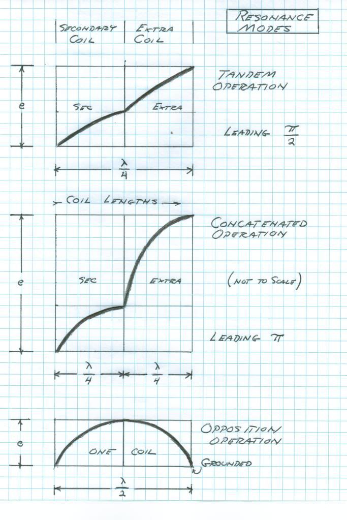
                              Two modes are possible for extra coil in relation with the secondary coil. Both involve quarter wave resonant rise, this the fundamental of resonant transformation. Its also known as constant potential to constant current transformation. A constant potential is a zero impedance (short circuit) a constant current is a zero admittance (open circuit). Departure from these zero values alters the coil distribution to something other than a quarter wave.

                              This quarter wave can exist in a distinct pair of manifestations. The first mode is when the quarter wave is distributed over the length of both extra and secondary windings as a whole, a pair of eighth waves let us say. This is the TANDEM mode. A multiplication in potential is derived hereby since the extra coil exhibits a higher transmission impedance thereby giving rise to a greater EMF between turns and thus a higher termination potential. All photos of my Bolinas and Integratron setups operated in this mode. It is the easy one to achieve.

                              The second mode of the extra coil and secondary coil connection involves two quarter wave distributions, one on each coil. This is not to be considered a half wave however. This mode is the CONCATENATED connection.It compounds the quarter wave resonant rise of the secondary coil with another quarter wave rise in the extra coil, hence a concatenated resonant rise. This is the holy grail of resonant transformer design and unheard of potentials may be gained in this manner. To derive this analytically is extremely difficult, it is an advance transmission line problem. It might not even be possible to calculate or even achieve this mode of resonance, but we are going to give it a try. Tesla dreamed of this mode but electrical knowledge was in its infancy in Tesla's Colorado years.


                              An excellent addendum to this is the John Miller Paper "Electrical Oscillations in Antennae and Induction Coils" provided with Eric Dollard's paper "Introduction to Dielectric and Magnetic Discharges in Electrical Windings". It can be seen here:

                              http://www.tuks.nl/pdf/Eric_Dollard_...0remake%29.pdf
                              There's a lot more information scattered in the 3 Eric Dollard threads but some is compiled here

                              http://www.energeticforum.com/eric-d...ompendium.html

                              As for the extra coil, Eric's (tentative) design assumes a propagation velocity of 157% in order to operate at the design frequency. Apparently others have done this or come close, but using solid copper wire and wooden dowels the maximum I ever got was about 129% (although you have to be very careful about the connecting wires from the oscillator to the extra coil to get the highest possible propagation - a coupling capacitor should be connected directly by its legs to the extra coil input because any additional lengths of wire have notable effects in bringing the frequency down etc). But all these are without any terminal capacitance, so the theoretical design must be on that basis. I then adjusted the wire length according to the measured propagation velocity, and obviously it's also possible to do the same with a terminal capacitance in place, but that introduces the problem of the size of the terminal capacitance.

                              But as can be seen in Eric's quote the first step is to tune the primary and secondary. The coupling should be adjusted for "maximum" magnification factor (in basic terms narrowest frequency response) so that in theory the slightest interaction at the designated frequency will set the coil into action, but obviously at some point it will become less efficient with the distance between the coils so that's another thing to be experimented with. John P (jpolakow) recently posted his experiments along these lines.

                              Assuming the secondary frequency is locked and the extra coil won't knock it off (at least too much), then it can be thought of as a basic AC source which puts the extra coil back into being considered the same as during first testing (alone). The problem is then what is the resonant frequency of the extra coil, either with direct connection to the secondary or through a coupling condenser, because the coupling capacitance and connecting wires etc affects its frequency. So the extra coil in place has some resonant frequency that is different to when its tested alone. So somehow you must discover what that would be, and ignoring a terminal capacitance, adjust the wire length so it ends up at the correct frequency when it's in place.
                              Last edited by dR-Green; 05-12-2014, 09:37 PM.
                              http://www.teslascientific.com/

                              "Knowledge is cosmic. It does not evolve or unfold in man. Man unfolds to an awareness of it. He gradually discovers it." - Walter Russell

                              "Once men died for Truth, but now Truth dies at the hands of men." - Manly P. Hall

                              Comment


                              • Cosmic Induction Generator update

                                Cosmic Induction Generator – The Early Work

                                Here is a short video showing some of the early work John Polakowski did on the Cosmic Induction Generator with Eric Dollard. This was last year during one of my early visits to Eric’s lab.


                                In the video, John is working on the coils and he and Eric are working the bugs out of the old Navy transmitters.


                                https://www.youtube.com/watch?v=_ZVMVtBdmsA


                                Please donate to John Polakowski’s Cosmic Induction Generator Indiegogo Campaign: http://igg.me/at/cosmicinductiongenerator/x/2343214


                                Come see John give a demo of the Cosmic Induction Generator at the 2014 Energy Science & Technology Conference – seats are running out so register now! 2014 Energy Science & Technology Conference | Exclusive conference with the Godfathers of the modern day free energy movement!


                                Cosmic Induction Generator – The Early Work | A & P Electronic Media – Digital Publishing by Aaron Murakami & Peter Lindemann
                                Sincerely,
                                Aaron Murakami

                                Books & Videos https://emediapress.com
                                Conference http://energyscienceconference.com
                                RPX & MWO http://vril.io

                                Comment

                                Working...
                                X