Announcement

Collapse
No announcement yet.

Eric Dollard

Collapse
This is a sticky topic.
X
X
 
  • Filter
  • Time
  • Show
Clear All
new posts

  • Originally posted by orgonaut314 View Post
    Don't know as the secondary coil should have an electrical and magnetic wave that is max on top. With these iron cores you get a lot of magnetic coupling but little electrical coupling? Not the Tesla wave that Dollard demonstrates with his analog networks. Or do you meen something else than an iron core?
    http://www.tuks.nl/pdf/Reference_Mat...20-%201977.pdf

    Somewhere in this wonderful document is a section on the parametric transformer. Thank you Arrend for providing this document, it helped me immensely.

    As you will see, you can use two "C" cores arranged in a special way to provide a small common but orthogonal flux path. In other words, the magnetic field of the primary and secondary are normal to each other. The primary acts to vary the reluctance of this common area. There is NO mutual magnetic inductance! Because of this, the secondary is free to oscillate just like a tesla coil.

    You can actually pump this with DC pulses and get extremely clean sine waves out of the secondary! You can use this to create harmonics as well!

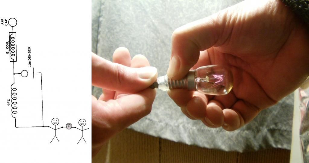
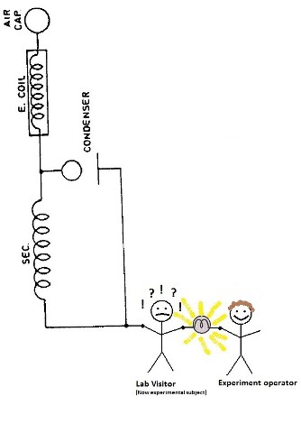
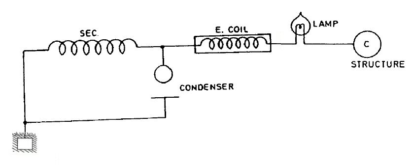
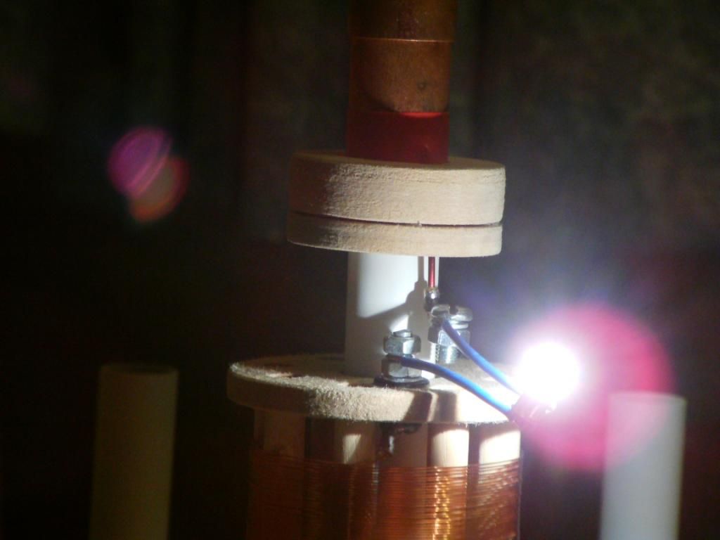
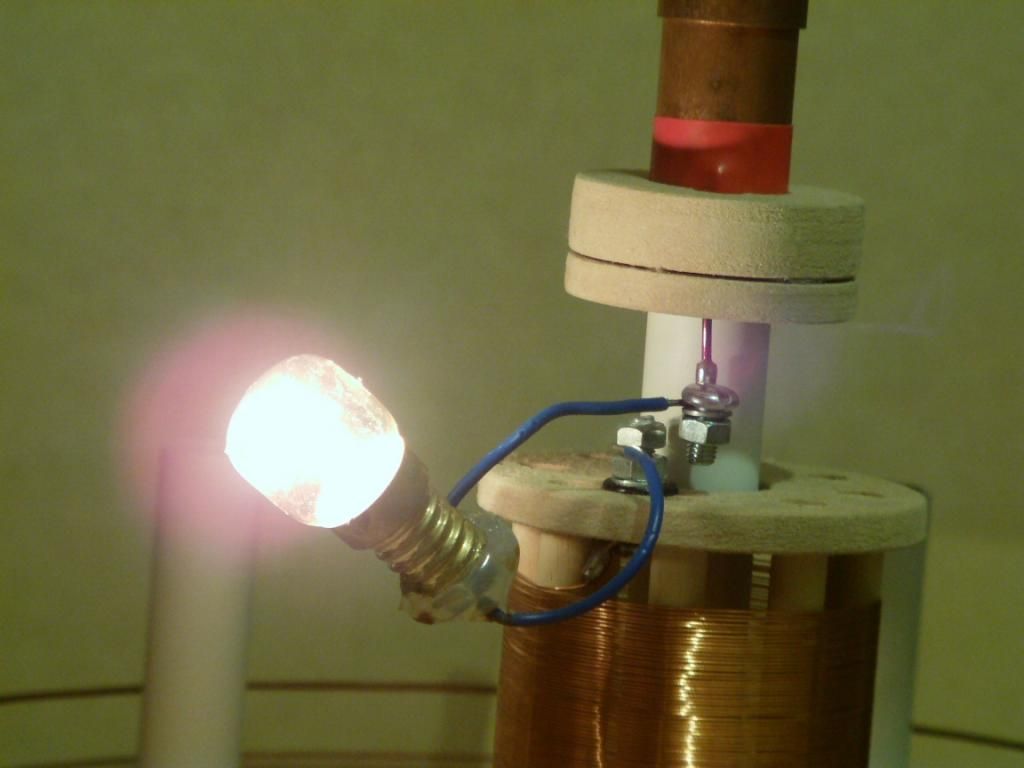
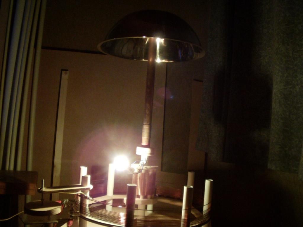
    If you ground one end of the secondary and attach a top capacitive load then you still have a quarter wave machine with the voltage anti-node on the top load just like a Tesla Coil.

    Find the secondary quarter wave resonant frequency (F) and pump the primary with (2F)

    Pure magic!

    Comment


    • Spiral Tesla Coil

      Recorded back in late February 2014. The testing of a single Spiral Tesla coil on CW 160 metres. The Telluric output terminal lighting vintage style, (not an antique) 25 watt filament bulbs (Same setup as previously posted etc.). Video quality isn’t great due to camera compensation and poor lighting / variable light etc.

      Spiral TMT test - YouTube

      I’ve posted this as my first U-tube video, more or less as a test, (a few minute video still took 8 hours upload)?? – Anyway when I’ve worked everything out, I’ll share some of my more recent tests. The sound of your own voice sounds goofy on video!

      Sputins
      "Doesn't matter how many times you kick the coyote in the head, it's still gonna eat chickens". - EPD

      Comment


      • Originally posted by Sputins View Post
        Recorded back in late February 2014. The testing of a single Spiral Tesla coil on CW 160 metres. The Telluric output terminal lighting vintage style, (not an antique) 25 watt filament bulbs (Same setup as previously posted etc.). Video quality isn’t great due to camera compensation and poor lighting / variable light etc.

        Spiral TMT test - YouTube

        I’ve posted this as my first U-tube video, more or less as a test, (a few minute video still took 8 hours upload)?? – Anyway when I’ve worked everything out, I’ll share some of my more recent tests. The sound of your own voice sounds goofy on video!

        Sputins
        Cool stuff, I like those vintage style bulbs. Quality/lighting looked fine to me. It takes you 8 hours to upload because it seems to be 1080p so the file is huge. You can probably change it to 720p in your camera settings, that will cut it down by nearly half. But unfortunately that will only apply to new recordings, everything else you've done so far will still take ages to upload.
        http://www.teslascientific.com/

        "Knowledge is cosmic. It does not evolve or unfold in man. Man unfolds to an awareness of it. He gradually discovers it." - Walter Russell

        "Once men died for Truth, but now Truth dies at the hands of men." - Manly P. Hall

        Comment


        • George "Friedrich" Handel


          Thank you for your support!
          SUPPORT ERIC DOLLARD'S WORK AT EPD LABORATORIES, INC.

          Purchase Eric Dollard's Books & Videos: Eric Dollard Books & Videos
          Donate by Paypal: Donate to EPD Laboratories

          Comment


          • Electromagnetic Induction and its Propagation

            New paper by Eric P. Dollard:

            Electromagnetic Induction and Its Propagation – This is a draft paper, which will be formatted better at a later time. The contents of this paper will be a part of the 2014 Energy Science & Technology Conference presentation called The Extraluminal Transmission Systems of Tesla and Alexanderson: Electromagnetic Induction and Its Propagation (pdf)

            New page on ericpdollard.com where a collection of his papers will be available as free downloads: Free Papers | Eric P. Dollard – Official Homepage
            SUPPORT ERIC DOLLARD'S WORK AT EPD LABORATORIES, INC.

            Purchase Eric Dollard's Books & Videos: Eric Dollard Books & Videos
            Donate by Paypal: Donate to EPD Laboratories

            Comment


            • Thanks Eric! The transmission line part gets clearer to me. Beautiful document. Now the aether part and the Faraday tubes. I have seen these pictures from the aether particle from the atom and from the human body and they all look the same.

              Comment


              • I rarely have visitors in the lab so I took the opportunity to do a two person experiment earlier. Connections as shown.

                http://www.teslascientific.com/

                "Knowledge is cosmic. It does not evolve or unfold in man. Man unfolds to an awareness of it. He gradually discovers it." - Walter Russell

                "Once men died for Truth, but now Truth dies at the hands of men." - Manly P. Hall

                Comment


                • Eric Dollard

                  Originally posted by Sputins View Post
                  Recorded back in late February 2014. The testing of a single Spiral Tesla coil on CW 160 metres. The Telluric output terminal lighting vintage style, (not an antique) 25 watt filament bulbs (Same setup as previously posted etc.). Video quality isn’t great due to camera compensation and poor lighting / variable light etc.

                  Spiral TMT test - YouTube

                  I’ve posted this as my first U-tube video, more or less as a test, (a few minute video still took 8 hours upload)?? – Anyway when I’ve worked everything out, I’ll share some of my more recent tests. The sound of your own voice sounds goofy on video!

                  Sputins
                  Very impressive ! What kind of powersupply do you use for this setup? Can you post a schematic ?

                  Comment


                  • Cred

                    Originally posted by dR-Green View Post
                    I rarely have visitors in the lab so I took the opportunity to do a two person experiment earlier. Connections as shown.
                    Very clever trick there dR-Green, I love it.

                    I don’t think we’ve seen that before on the forum!

                    I rarely have lab visitors either, but when the next appropriate visitor comes around I must give that one a try! - That is if I can find an enthusiastic experimental subject! Lol, It will probably have to be me or someone else who’s less than enthusiastic!

                    A result like that deserves a pictorial response!


                    How about using the receiver coil (or CIG) with certain bulbs and experimental subjects in between?


                    Credit given
                    "Doesn't matter how many times you kick the coyote in the head, it's still gonna eat chickens". - EPD

                    Comment


                    • Block Diagram

                      Originally posted by Prio View Post
                      Very impressive ! What kind of powersupply do you use for this setup? Can you post a schematic ?
                      Hi Prio
                      Thanks.

                      A schematic of what part? There isn’t a single schematic (not as yet). There is a system of schematics, each part takes its required learning. There are no real short-cuts. The people building this stuff have done so out of extensive research, study and hard work. I wasn’t handed a schematic either, I had to learn about all of these things on my own. Although I asked some knowledgeable people certain questions and the answers from them lead me in the right direction.

                      So what I can give you is a block diagram of my particular setup as in the video.


                      So if you build yourself a transmitter, either using vacuum tubes (As Eric recommends) or use solid state as dR-Green has done. The transmitter will need a VFO & the transmitter needs its power supply. Then you’ll need a Pi-network or other impedance matching network. Then you have the Primary Tank Circuit, (mine is 3T primary coil with ~900pF capacitor). Next is the Secondary coil. Build it as per Eric’s instructions (mine happens to be in spiral form), use the 20% height to width ratio plans is better. Then you have the terminal capacitance (reflector) and then you have the monopole telluric output. The Extra coil is omitted in this particular diagram. A Radio licence is required unless you can dis-able any air transmission.

                      If you use the forum, do your own research & study, have the required building skills, ask the right questions about each of the puzzle pieces, you too could build your own real life Tesla Transformer. Good luck.

                      Sputins.
                      "Doesn't matter how many times you kick the coyote in the head, it's still gonna eat chickens". - EPD

                      Comment


                      • Eric Dollard

                        Originally posted by Sputins View Post
                        Hi Prio
                        Thanks.

                        A schematic of what part? There isn’t a single schematic (not as yet). There is a system of schematics, each part takes its required learning. There are no real short-cuts. The people building this stuff have done so out of extensive research, study and hard work. I wasn’t handed a schematic either, I had to learn about all of these things on my own. Although I asked some knowledgeable people certain questions and the answers from them lead me in the right direction.

                        So what I can give you is a block diagram of my particular setup as in the video.


                        So if you build yourself a transmitter, either using vacuum tubes (As Eric recommends) or use solid state as dR-Green has done. The transmitter will need a VFO & the transmitter needs its power supply. Then you’ll need a Pi-network or other impedance matching network. Then you have the Primary Tank Circuit, (mine is 3T primary coil with ~900pF capacitor). Next is the Secondary coil. Build it as per Eric’s instructions (mine happens to be in spiral form), use the 20% height to width ratio plans is better. Then you have the terminal capacitance (reflector) and then you have the monopole telluric output. The Extra coil is omitted in this particular diagram. A Radio licence is required unless you can dis-able any air transmission.

                        If you use the forum, do your own research & study, have the required building skills, ask the right questions about each of the puzzle pieces, you too could build your own real life Tesla Transformer. Good luck.

                        Sputins.
                        Thank you very much for the time taken to write this comprehensive answer. Your block diagram is most helpful to get an overview for the Tesla transformer. I try hard to get a comprehensive knowledge of this technology, but when reading trough the forums as an amateur I am not able to judge what is important, less important and useless. So to get an overview when reading through the forums I have to condense all the useable knowledge until I can envision a starting point to build a specific transformer setup. So I have to envision by myself a specific setup, design it and build it. When I have seen your video on youtube, I thought that could be the set up I want to start to replicate.

                        There is still the question, what is the engineering goal, what can you expect and achieve with this set up?

                        Thank you very much for your time !

                        Comment


                        • whats pi-network? is pi network, like 3.17?

                          Comment


                          • Originally posted by ldrancer View Post
                            whats pi-network? is pi network, like 3.17?
                            A Pi network is a capacitor and inductor arrangement that looks like π, or the character Pi. It is an impedance matching network to match a source to a load impedance.

                            http://www.teslascientific.com/

                            "Knowledge is cosmic. It does not evolve or unfold in man. Man unfolds to an awareness of it. He gradually discovers it." - Walter Russell

                            "Once men died for Truth, but now Truth dies at the hands of men." - Manly P. Hall

                            Comment


                            • Originally posted by Sputins View Post
                              Very clever trick there dR-Green, I love it.

                              I don’t think we’ve seen that before on the forum!

                              I rarely have lab visitors either, but when the next appropriate visitor comes around I must give that one a try! - That is if I can find an enthusiastic experimental subject! Lol, It will probably have to be me or someone else who’s less than enthusiastic!

                              A result like that deserves a pictorial response!

                              How about using the receiver coil (or CIG) with certain bulbs and experimental subjects in between?

                              Credit given
                              Thanks! Hehe I like the diagrams, although I think the experimental subject will have question marks floating around his head wherever he stands! It will be even better with your higher power setup. This is the second time I've done it, I usually stand in the middle myself to spare the visitors from plasma burns and what not. We also used 8x 1.5V grain of rice/wheat bulbs in series which looked more impressive/brighter than the big bulb, but my friend was nervous so the moment he started to feel a bit of heat he let go of the thin wires, so that only lasted a few seconds. I doubt he was getting plasma burns after the current had passed through me, that may have been caused by the bulb heating up as normal, but I had not mentioned what kind of effects I usually feel to see if he would comment on anything. But as you know thin wires are not usually the parts you want to hold on to.

                              This was the first attempt at the same thing a couple of years ago, using spark gaps back in the day.

                              A Bulb In Hand(s) - YouTube

                              A receiver works with a bulb and one person in between, so I expect it should work just the same with more people. The only question is the amount of power. Working a speaker on the receiving end is certainly possible.

                              It should be very good to see these things with a bit more power used!
                              http://www.teslascientific.com/

                              "Knowledge is cosmic. It does not evolve or unfold in man. Man unfolds to an awareness of it. He gradually discovers it." - Walter Russell

                              "Once men died for Truth, but now Truth dies at the hands of men." - Manly P. Hall

                              Comment


                              • This is an updated experiment with the slightly higher power amplifier compared to last time, and with the bigger capacitance terminal/tuned extra coil. Last time a 1.5V grain of rice bulb was barely lit, this time it popped within seconds.

                                Basic setup is somewhat similar as shown in Colorado Springs Notes page 360, the difference being that my extra coil is connected to the top of the secondary rather than a ground plate.


                                Actual connections


                                28V bulb, transmitter not at full power


                                28V bulb, all the lab lights off


                                Within 3 minutes the 28V bulb had blown


                                240V 15W bulb


                                240V 15W bulb, all the lab lights off

                                http://www.teslascientific.com/

                                "Knowledge is cosmic. It does not evolve or unfold in man. Man unfolds to an awareness of it. He gradually discovers it." - Walter Russell

                                "Once men died for Truth, but now Truth dies at the hands of men." - Manly P. Hall

                                Comment

                                Working...
                                X