 Tweet
Tweet
Machine
Seven will work and I guess when you are done, we will know if eight would have worked also. I use a tongue depressor to push wires down. First pressing far right then left and finish with turning the stick crosswise in a 'X' pattern until it stays down. Good luck and remember that ten pounds pull on that wire is not too much. That is the feel of hanging a full ten pound wire spool with one wire and holding it up in one hand.
Dana
 . From one of UFOs early videos, the positive from the generator tab was connected to the negative tab of the motor, also with the battery negative. The voltage reading was taken from that tab to the motor input positive- so should I use that output to a battery or whats the best way to wire it?
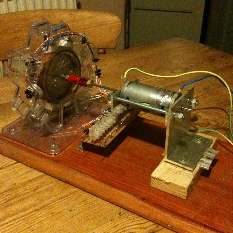
 [/IMG]


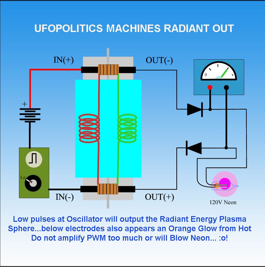
 ...Also SHE will spark with a Motor Ground Chassis...even though...all coils are insulated from ground...
 [/IMG]
 [/IMG]
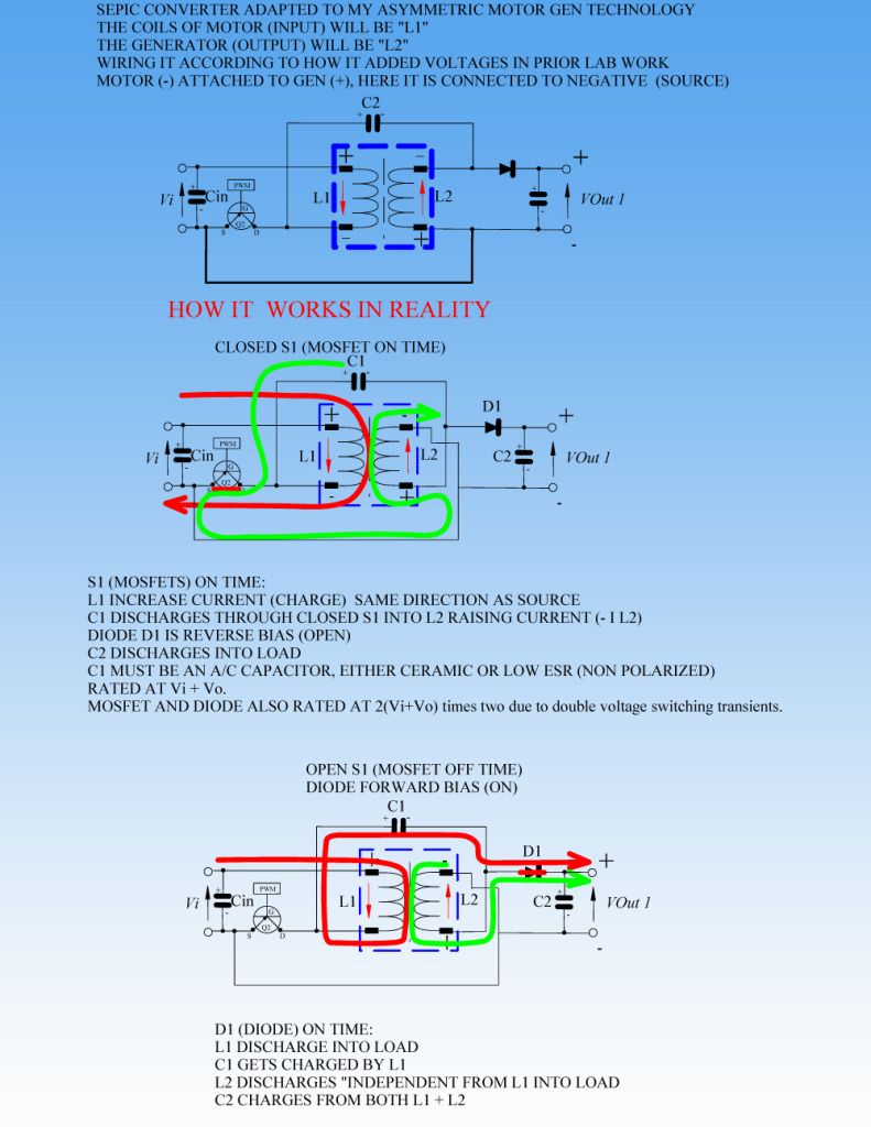
 I will ponder on it.
Comment