Announcement

Collapse
No announcement yet.

My Asymmetric Electrodynamic Machines

Collapse
X
 
  • Filter
  • Time
  • Show
Clear All
new posts

  • Language in Common...

    Originally posted by Lester444 View Post
    Hello UFO,

    I'm trying to understand the relationship between angular velocity (rpm-wise) relative to pulse width and pulse frequency. I hope you don't mind my questions:

    1. I assume that as the rpm goes up, the frequency of the pulses (from the FET) should go up also; is this a correct assumption for your machine?
    Shouldn't it be the other way around?...As the FET pulses go up...the RPM's go higher...FET's Drive Machine...Machine do not drive FET's...
    But yes, that is the way it goes, just like in any Symmetrical Pulsed Motor Controller...

    2. Can you please shed more light on the "timing" relationship with regards to the pulse (one single pulse) and the commutator (one winding pair)?
    I mean the synchronization of the VOLTAGE pulse (rising edge & falling edge, the turning-on and turning-off of the FET) relative to the brushes' positions on the commutator.
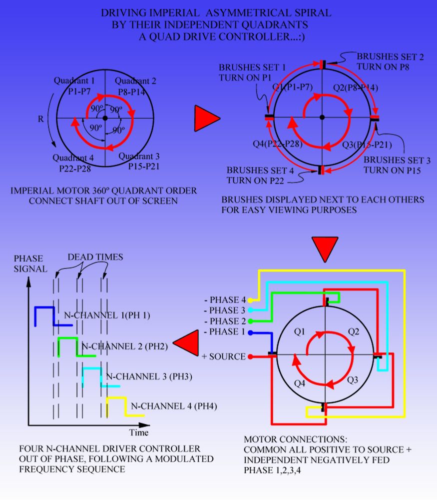
    Ok, first off, let's set the "Roll" of each system, the FET's Pulses Drive the Motor, now the Motor is an endless spinning Spiral Cycle, and FET's could "catch on" at ANY given Point within the 360º Quadrant, and from there on, they will take over the feed control.

    Now, getting more technical...This Machines express a common Language as the FET's do...and that is Frequency (Hz)...for a given speed/torque output they have a close range of Hertz up to KHz...So say we want to retain a range @3600 Steady RPM's...so let's Scope Motor Output for Frequency (using Input will get your own FET's Pulses... ) So the perfect Machine expression (as isolated from Input) will come from its output naturally reversed pulses...like a response to the Input...understand me so far?

    3. As to the SEPIC topology, can you please tell us the timing (phase relationship) of L1 relative to L2? From what I understand L1 and L2 are on different rotor poles and so can not be regarded as being on the same core (timing-wise) as in your drawing. L1 & L2 are independent coils as you have pointed out and so perhaps should be presented (drawn) independently also.
    Oh, yes, they are Independently energized just like the Inductors on a SEPIC...However, they DO are mounted on same core...and that is the Armature Core, Lester...
    I have run my BOSCH with the simplest SEPIC...there could be...a 555 Oscillator with FET Drains...a suitable AC Metalized Cap, and an Ultrafast NTE576 Diode...Motor runs excellent...as output is also great. Of course, have to realize the actual SEPIC...is spread all over...

    It seems to me that some sort of timing actuator (optical encoder, hall-effect gear-tooth sensor, etc.) is mandatory at this time. I don't suppose you simply want to "fire away" with fixed pulses and hope it hits the mark, right?
    Yes, indeed it could be done that way...I mean, speed sensors exist and so ...that can translate into Mileage, Speed taken into Miles Per Hour... read outs...or Hours of running time, etc,etc...We could also use them for sensors to keep desired speed...However, please review the first part where I mentioned about the common Hz Language...from Input-Output...then we realize no speed sensor would be required IF we have the system read based on Frequency instead of speed...so, all we do is to raise Frequency where the parameters (speed/hertz) meet our requirements...right?


    Thanks!

    Lester444

    Regards

    Ufopolitics
    Principles for the Development of a Complete Mind: Study the science of art. Study the art of science. Develop your senses- especially learn how to see. Realize that everything connects to everything else.― Leonardo da Vinci

    Comment


    • The Guy is no longer on Electrical...

      Originally posted by prochiro View Post
      UFO/JohnS @All

      This is a video of a homemade motor controller out of scrap parts.
      This video is about a completely homemade high voltage high amperage DC motor controller, the controller can perform at voltages above 120v and 600A, on this video is a first test run where the controller was tested at high voltage, the next test will be a performance and load test in the electric car car.
      Homebuild DC motor controller - YouTube

      Enjoy
      Dana
      Hey Prochiro,

      Nice Vid Dana...but unfortunately...read the comments there...
      The Guy is no longer on Electrical Stuff...(now on Alcohol and other Gas deals, check newer videos)...say He threw everything away...

      Regards


      Ufopolitics
      Principles for the Development of a Complete Mind: Study the science of art. Study the art of science. Develop your senses- especially learn how to see. Realize that everything connects to everything else.― Leonardo da Vinci

      Comment


      • @UFO
        I did read that and thought it was strange. I saw that while bumming around the net. Sometimes a person with talent can stay on track and sometimes not. We all are not going to let you get side tracked Dear UFO. I did however find the neatest way to cool as many fets as you want, even 40 of them. A small computer fan is fastened to the end of a rectangular aluminum tube and the fets are aligned along each side. Air traveling thru the tube cools the fets vary well.
        You can see it at the vary first and vary last of this video.
        Dana

        Brushless controller schematic Hall sensor - YouTube

        Here is his homepage with controller diagram.
        DC Motor Speed Controller PWM 0-100% 400Hz – 3khz Freq « DIY Electric Car, Masina electrica ro
        Last edited by prochiro; 01-07-2013, 05:40 AM. Reason: Add address
        "Today's scientist have substituted mathematics for experiments and they wander off through equation after equation and eventually build a structure which has no relation to reality."
        Nikola Tesla

        Comment


        • Bedini was doing simila in 1984

          G'Day UFO,John stone

          New Page 1

          Bedini Did this 1984
          Further down the page go to next page and the first link is this link

          BEDINI'S FREE ENERGY GENERATOR

          His site may give some Ideas

          Regards Kogs

          Comment


          • Thanks

            Hi UFO / Prochiro

            Thanks for your help on previous post re connections - will report back.

            Regards

            John

            Comment


            • Originally posted by prochiro View Post
              I did however find the neatest way to cool as many fets as you want, even 40 of them. A small computer fan is fastened to the end of a rectangular aluminum tube and the fets are aligned along each side. Air traveling thru the tube cools the fets vary well.
              You can see it at the vary first and vary last of this video.
              Dana

              Brushless controller schematic Hall sensor - YouTube

              Here is his homepage with controller diagram.
              DC Motor Speed Controller PWM 0-100% 400Hz – 3khz Freq « DIY Electric Car, Masina electrica ro
              Hi Dana,
              nice setup with effective cooling!
              The FET driver is quite similar to the suggestion from Lester. So we have proof that it is right for high amperage.
              We have built generators in order to control switching with PWM. I will make up my mind in order to combine those FET driver clusters with microprocessor. Loading a predefined program is dead easy so anybody can replicate it. We need program control in order to get more sphisticated and .... SW is much more easyer to replicate.
              I know Nico8K has similar micro setup on his desk. Stay tuned.
              rgds
              JohnS
              Experts spend hours a day in order to question their doing while others stopped thinking feeling they were professionals.

              Comment


              • Thank you for your reply UFO!

                Lester444

                Comment


                • JohnStone
                  Here is a site you may find interesting. A 160A , 13 to50V DC motor HDrive controller with all the math done.

                  Robot Power Products - Open Source Motor Control (OSMC)

                  Dana
                  "Today's scientist have substituted mathematics for experiments and they wander off through equation after equation and eventually build a structure which has no relation to reality."
                  Nikola Tesla

                  Comment


                  • Proposal: Let's continue driver discussions on the other thread "My motors got me..." inorder to focus an motor replications at this place.
                    Experts spend hours a day in order to question their doing while others stopped thinking feeling they were professionals.

                    Comment


                    • Originally posted by thaelin View Post
                      Just be aware, these have bronze bearings, not ball bearing. That bearing is rated for the factory speed and you are going to way over rev it doing this. Did a few motors in the past with them and typical they ship within 2 days of the order.

                      Let us know what the rotors look like and measurements.

                      thay
                      !0 pole rotor, not epoxy dipped but has paper sleeves and plastic inserts on ends.

                      When working to get the commutater free I tried hard blows with a soft heavy mallet to try and get the rotor to move on the shaft but it would not move.

                      The shaft is 7.5in x 5/16, rotor is 1.5in long, 1 11/16 D, Case is 4 in long, 2.5 in D.

                      The end cap with brushes come out easily because of through the case bolts, original bolts are 10-32, 4in.(3/16in) I found 10-24 threaded rod to extend.

                      The original wire is .019inD, 24.5AWG (?)

                      What would be best size to wind 10 pole asym?
                      I have #28AWG, think that #25 would be better If someone else does these motors I can give tips for removing the comm.

                      The mags have tabs on both sides. Have yet to remove them for "welding".


                      bro d

                      Comment


                      • Quad Channel Drive For Imperial

                        Hello to All,

                        I know, this is kind of Crazy...unusual, that has ever been out...but if we all realize neither My Asymmetrical Windings and Motors have...so here I go...


                        [IMG][/IMG]


                        At First sight, it looks very complicated, but it is not...
                        It is just a Four N-Channel MOSFET's...out of Phase...and following a Sequence that will turn On the Four Quadrants at Motor...but with a difference in Time...
                        When I was playing with the Two Switches...and found out by turning them sequentially by a different timing...I notice a huge reduction in Amperage Draw...however, this fact did not occur if I turned them both simultaneously...

                        Now, all parameters here would need to be regulated...to precisely and accurately control Motor Speed/Torque and Amperage Draw...and "Popular Speaking"...We need to leave "Unsatisfied" the Turning Time On of Each Quadrant, before it reaches the next Input...like an "Idle" or Dead Time Stage...even though they will continue to "Automatically Disconnect" at each Pulse On.

                        What we are doing here, simply...is avoiding the heavy population or avalanche of electrons in the full 360º Cycles, by Limiting their Feeding Time per Quadrant...Therefore "Population" or Amperage will be reduced at each Terminal Gate considerably...
                        Main purpose is that they will be low in population/strength by the time flow reversal occurs...

                        The Diagram I displayed is based on the original winding sequence We did ...or...P1 through P28...BUT, it not necessarily need to be AND IT WILL NOT be like that either...The Starting Point of the "Race" could happen at any part of the Motor Quadrant positioning related to the Phase 1 Feed, or Starting Stage...Motor will "catch up" from there on...


                        I know this Post should be on the other Thread...However, We are doing a "FUSION" here...between Motor Windings-Input and Driving Controllers...Therefore, We could split apart this Issue later on, where We could discuss in detail the Electronics Side in the Other Thread...as we do the connections and Motor Timing here...is up to you guys...so you let me know.

                        @Lester444, You triggered this Post, when You wanted to understand the Angular Velocity related to the FET's Signals...so, here you all have it.

                        For those of You, who are not familiar with the Three Phase DC Drivers applied to Brush-Less DC Motors...please review them...since it is kind of similar, when it comes to Frequencies Off Time Phases...and dead times...and it will help you all understand this mode...However, must realize that here we are turning on in a similar way...OPEN Coils...not CLOSED by a Star or Delta Winding Symmetrical System...big difference Guys!...Our Electronics will NOT receive the Reverse Huge Spikes that destroy our pulse circuit like in a CLOSED LOOP Occurs...

                        As this system will move Us into another set up, where we will not require brushes...like an Out Runner type but Asymmetrical Motor Stator driving outer PM Rotors...However, that is later, later on...


                        Regards to All


                        Ufopolitics
                        Last edited by Ufopolitics; 01-08-2013, 07:44 PM.
                        Principles for the Development of a Complete Mind: Study the science of art. Study the art of science. Develop your senses- especially learn how to see. Realize that everything connects to everything else.― Leonardo da Vinci

                        Comment


                        • Hi UFO,
                          For those of You, who are not familiar with the Three Phase DC Drivers applied to Brush-Less DC Motors...
                          That rings a bell... Is it not what is used for RC motors? The driver (ESC) could therefor be used to drive the brushless motor and are available cheap on Ebay.

                          Keep up the good work,

                          Michel
                          http://www.youtube.com/watch?v=jeYscnFpEyA

                          Comment


                          • Three Phase...Vs Four Phase...

                            Originally posted by Michelinho View Post
                            Hi UFO,


                            That rings a bell... Is it not what is used for RC motors? The driver (ESC) could therefor be used to drive the brushless motor and are available cheap on Ebay.

                            Keep up the good work,

                            Michel

                            Hello Michelinho,

                            It is similar, but not same...the ESC (Electronic Speed Control) is a Three Phase...where actually only Two Phase are the one feeding Motor...while third acts like a channel to the positioning sensors...

                            What I am displaying above is a Four Phase...of All feeding N-Channels...switching on, at different times in a sequenced whole 360º Cycle Frequency...

                            Two different scenarios...sorry...


                            Regards


                            Ufopolitics
                            Principles for the Development of a Complete Mind: Study the science of art. Study the art of science. Develop your senses- especially learn how to see. Realize that everything connects to everything else.― Leonardo da Vinci

                            Comment


                            • Depends Donald...it depends...

                              Originally posted by Donald Haas View Post
                              !0 pole rotor, not epoxy dipped but has paper sleeves and plastic inserts on ends.

                              When working to get the commutater free I tried hard blows with a soft heavy mallet to try and get the rotor to move on the shaft but it would not move.

                              The shaft is 7.5in x 5/16, rotor is 1.5in long, 1 11/16 D, Case is 4 in long, 2.5 in D.

                              The end cap with brushes come out easily because of through the case bolts, original bolts are 10-32, 4in.(3/16in) I found 10-24 threaded rod to extend.

                              The original wire is .019inD, 24.5AWG (?)

                              What would be best size to wind 10 pole asym?
                              I have #28AWG, think that #25 would be better If someone else does these motors I can give tips for removing the comm.

                              The mags have tabs on both sides. Have yet to remove them for "welding".


                              bro d
                              Hello Donald,

                              You have a Ten (10) Pole Rotor...right?
                              So You have two ways to wind it Asymmetrically...
                              1-Dual Pentagons
                              2-P10 Configuration

                              The Pentagon design requires less wire...10 Coils.
                              The P10 takes 20 Coils Total...

                              So, it does depends...the Pentagon you could afford to use a coarser wire...not on P10 Format.

                              Dual Pentagon is not as fast as P10 is, but it has great Torque.

                              So You decide there...


                              Regards


                              Ufopolitics
                              Principles for the Development of a Complete Mind: Study the science of art. Study the art of science. Develop your senses- especially learn how to see. Realize that everything connects to everything else.― Leonardo da Vinci

                              Comment


                              • Hello everyone,

                                Well, UFO, I've got the generator wound. That was alot more work then the motor, at least in my opinion. 7 turns of 19.5 ga. I would not try 8 turns .

                                It weighs 8.765 kg. I'll post some pics tonight or tomorrow.

                                Also got some steel bearings to replace imperials. Now I just gotta wait for stators, and it's go time.

                                Machine

                                Comment

                                Working...
                                X