 Tweet
Tweet
There Here!!!
Hello UFO, and all, my laminations have finally arrived.
I had them lasercut, it was a lot cheaper than watercutting, over here anyway.
Would love to show pics but attachments are full.
I have dropbox on computer now but buggered if i can work out how to use it. Probably Kids in preschool now this s--t.
Any way Love to all, Cornboy.


 [/IMG]
 , set up the motor, with new charged batteries, at least they read full, 37 v. Initially the motor did 2200 rpm, them I adjusted, cw, rpm went up to 2900, then adjusted up as far as magnet holder would allow and got the rpm to 3400, not alot of sparking, except at shut off. it is about the width of brush ahead of bisector, next would be to mod the brush assemble to move it a little farther but, not now, it did work good though. The gen initally did 900 rpm, adjusted ccw and got up to 1000 rpm, it seems to work good not alot of sparking, but I need to spend another 4-6 hours on adjusting I could see.


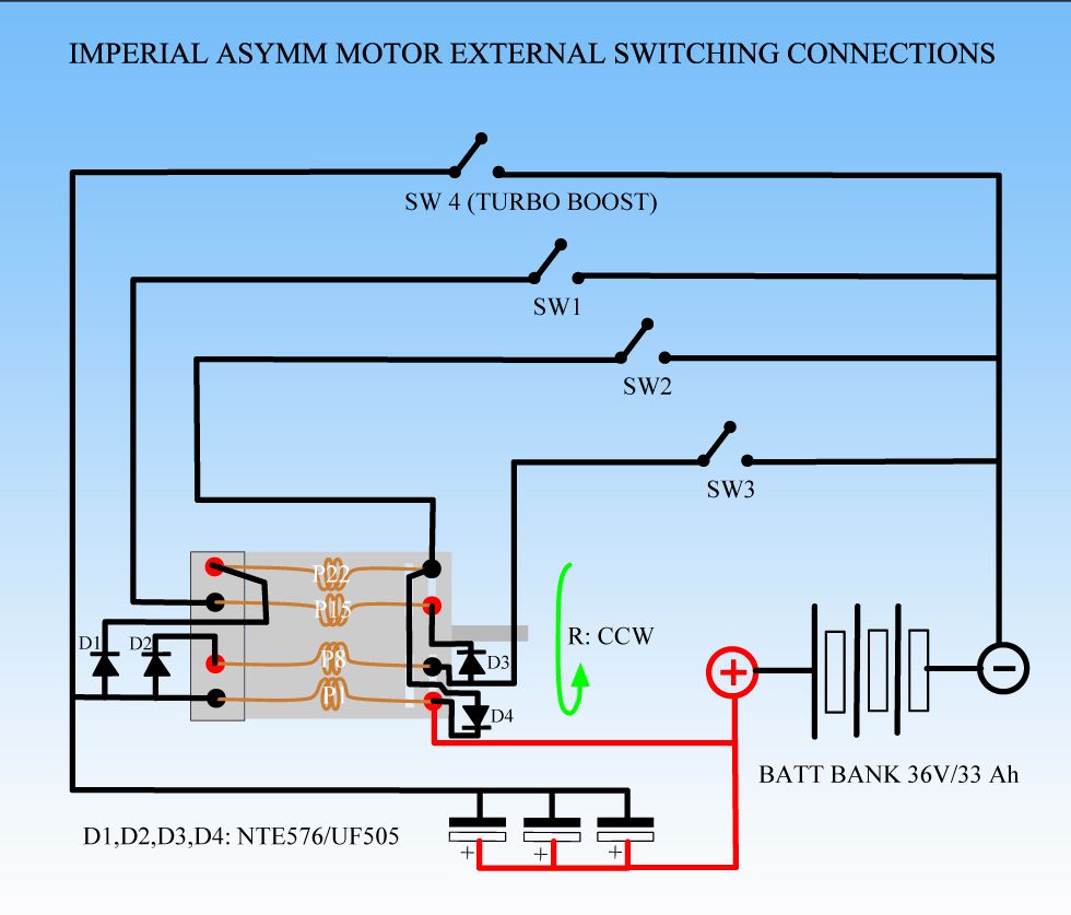
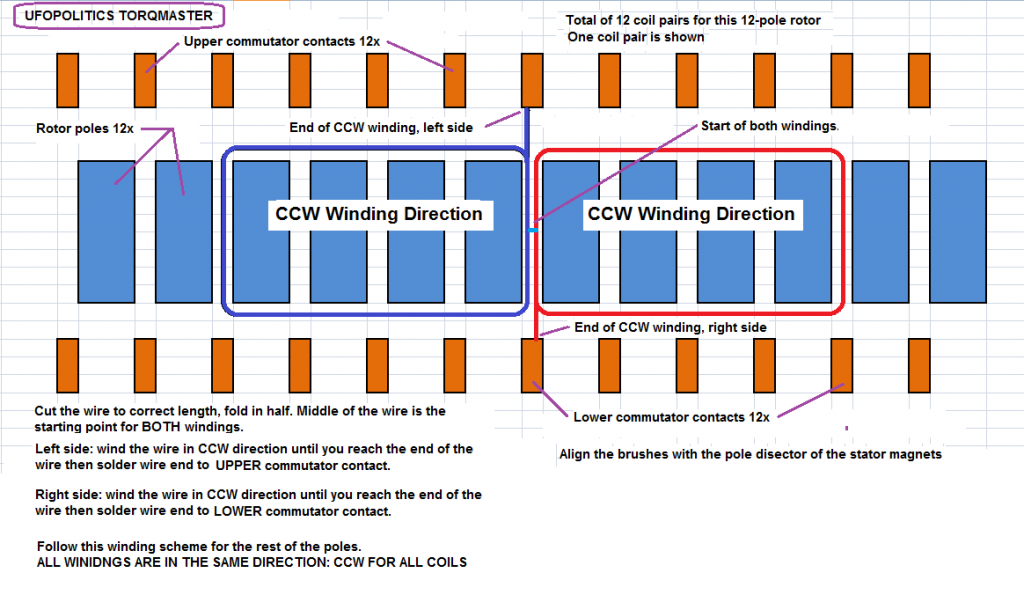
 Reference document: ASYMMETRIC WINDING v 01 Nov 2012.pdf page 15/27
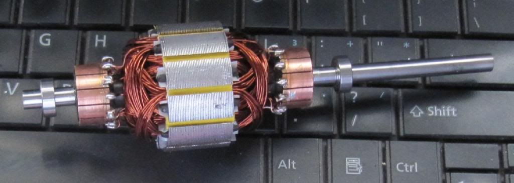
Comment