Announcement

Collapse
No announcement yet.

My Asymmetric Electrodynamic Machines

Collapse
X
 
  • Filter
  • Time
  • Show
Clear All
new posts

  • Originally posted by Cornboy 555 View Post
    ...
    Would love to show pics but attachments are full.
    I have dropbox on computer now but buggered if i can work out how to use it. Probably Kids in preschool now this s--t....
    • Have you got a drive on your PC called "dropbox" along a blue logo? If not you did not install dropbox on your PC - perform it!
    • If you have this dirve available you can copy any file from another place and go to dropbox / public and drop your file there there. You might want to generate a sub directory in order to organize your files.
    • Right click on that file and chose to "copy public link"
    • Write your post and if you want to insert the pic click on the logo above your text "insert pic" (square with mountain & sun) and drop the link memorized before by pressing CTR V.
    Experts spend hours a day in order to question their doing while others stopped thinking feeling they were professionals.

    Comment


    • Originally posted by Cornboy 555 View Post
      Good on ya Lester, your'e a champ, one question if you would be so kind, is it more important to have same wire length or same number of turns,? Can't find an answer anywhere.

      Warm Regards Cornboy.
      Hello Cornboy,

      Same number of turns result in same ampere-turns per pole, so presumably that results in equal magnetic field strengths, but, since the wire lengths are unequal then the wire resistance will also be unequal.

      Conversely, same wire lengths would result in same resistances for each pole but would also result in unequal ampere-turns so..........

      I honestly don't know.

      Would be good to hear UFO's take on this.

      Lester

      Comment


      • Originally posted by JohnStone View Post
        Please make clear on what imagination you refer to be bisector.
        Hello John,

        I meant the pole bisector of the MAGNET on the stator, the imaginary line right at the center of the magnet's face. I will use that as a starting point then tweak the brush position for best running. Sorry for not being clear about that.

        Thanks for the links!

        Lester
        Last edited by Lester444; 01-18-2013, 12:23 PM.

        Comment


        • Originally posted by Lester444 View Post
          Hello John,

          I meant the pole bisector of the MAGNET on the stator, the imaginary line right at the center of the magnet's face. I will use that as a starting point then tweak the brush position for best running. Sorry for not being clear about that.

          Thanks for the links!

          Lester
          Yes well. We want to make knowledge transfer easy. Your diagram is great and can be made perfect:
          Will it be possible to mark in your digram the current plus side of the wire (I assume bottom), the noth pole of the half winding (I assume left hand) and add the bisector (dotted line) through the center of the rotor north pole and annotate it with "bisector north".
          Will it be possble to repost the diagram in order to make life more easy for others.

          Your remark: "Align brushes with the pole bisector of the stator magnets" was may miscomprehension before discussing with UFO.

          This rotor north bisector shall be aligned with magnet north bisector of the stator. Then we can easily preempt on where the brushes shall be positioned. I had to rearrange the wires in respect to commutator segements later on because my brushes were mechanically at another place related to UFOs diagram.
          Last edited by JohnStone; 01-18-2013, 02:04 PM.
          Experts spend hours a day in order to question their doing while others stopped thinking feeling they were professionals.

          Comment


          • Originally posted by Lester444 View Post
            ... Same number of turns result in same ampere-turns per pole, so presumably that results in equal magnetic field strengths, but, since the wire lengths are unequal then the wire resistance will also be unequal.
            Conversely, same wire lengths would result in same resistances for each pole but would also result in unequal ampere-turns so..........

            I honestly don't know. ...
            Me too. But I feel it is much more to it:

            We know two types of resonance:
            • LC resonance is what we imagine if we talk of resonance.
            • There is a resonance available regarding wire length. There is a patent out there pondering on what happens if we build coils haveing both resonances aligned to the very same frequency. (gigantic coils!)

            The latter resonance is never regarded in usual electromagnetic machines. If we talk of heavy pulsing our machines we - of course - make use of resonance ringing in any respect. As long we do not know HOW exactly assymmetric motors operate (or magnetic transfer and reaction in all respect and in general) it is wise to make windings same length if possible.

            Our notion that current in a coil produces magnetism and this magnetism transfers energy to a secondary winding is extremely superficial. There are simplified thinking models regarding this matter and this seems to be a natural law. It is as if we say: if you are cold you get a cold - simplified - yes- it is true for most cases. But what about IF NOT? Detect another "law of nature" not known before.

            Research deals with facts NOT known well and therefore it is wise to regard some minute details up the the time when we know they are not relevant - but if they are important we grow them up. But before we do not know where those parametrs live.

            Another example: There is a patent out there talking about wires being coated with semiconducting layers. Electrons are told to travel supraluminal in those layers being accelerated by an obscure energy (not by input power). If they dive back into the wire they forward their kinetic energy to other electrons living there and thus the output is OU. (simply said: OU transformer by using coated wire) Copper oxide is semiconducting! Now imagine a poor boy tinkering with some oxidized wires from scrap and gets OU. We buy new shining wires from the shop and try same setup - nada. What do we think? Do we regard this poor boy to be a inventor?

            We are blessed to have UFO as instructor but please regard this thread to be possibly a place where we may discover much more than UFO can teach just now.
            You can teach known matters only!!!!
            JohnS
            Experts spend hours a day in order to question their doing while others stopped thinking feeling they were professionals.

            Comment


            • Originally posted by Cornboy 555 View Post
              Deleted some attachments so could load pics, i will get the hang of it soon, slow learner.

              Regards Cornboy.

              Hello Cronboy, great stuff. New UFO generator of the 2103. Looking forward to new horizons.

              Warmest regards

              light

              Comment


              • Cornboy, use photobucket.com.


                Originally posted by Cornboy 555 View Post
                Deleted some attachments so could load pics, i will get the hang of it soon, slow learner.

                Regards Cornboy.

                Comment


                • Hello Lester

                  Originally posted by Lester444 View Post
                  Dear all,

                  While trying to understand how to wind a 12-pole Torqmaster rotor, I found a way to make rotor winding less confusing for me: I flattened out the rotor & commutators on paper then drew how the wires should be wound onto the poles. See drawing below.

                  I planned on using pre-cut wire lengths instead of counting turns and while doing this I also found out that if you start winding at the middle of the wire you must wind in the same direction for both poles. This results in a north pole / south pole for the 2 windings, consistent with how the poles should be wound. After winding the first coil pair I then checked the 2 poles with a magnet and confirmed that they are indeed North & South.

                  The only difference is now the brushes should be aligned with each other and not rotated 180-deg (relative to each other) but I thought that to be a minor inconvenience since I will be fabricating adjustable brush mounts anyway.

                  If you find anything wrong with this method please let me know.

                  Thank you.

                  Lester


                  Hello Lester,


                  Take a look at this Diagram...

                  [IMG][/IMG]


                  Wiring is the same exact deal...it depends from what Point Of View you look at it...

                  In ALL Three ways (Starting Points)...The Coils are Seen Completely Different winding directions...HOWEVER, they are ALL exactly same final results...

                  Your Point to look at it (2), I understand is because you have gone by Length of Wire...so you start from center wire between two Coils...

                  But they are all the same thing.

                  The Positioning of Brushes have nothing to do with this different Views...BUT, with the Commutator Elements you have chosen to be related to Stators and Armature Poles positioning...that is why I have rendered so many different Diagrams that reflect Brush Positioning related to Stators and Rotor Poles disposition.


                  Regards


                  Ufopolitics
                  Principles for the Development of a Complete Mind: Study the science of art. Study the art of science. Develop your senses- especially learn how to see. Realize that everything connects to everything else.― Leonardo da Vinci

                  Comment


                  • Mag 3

                    Originally posted by Cornboy 555 View Post
                    Deleted some attachments so could load pics, i will get the hang of it soon, slow learner.

                    Regards Cornboy.

                    Hello Cornboy,

                    Now that is a BEAUTY!!

                    [IMG][/IMG]


                    [IMG][/IMG]


                    [IMG][/IMG]


                    That will BE an Awesome Machine My Friend!!


                    Regards


                    Ufopolitics
                    Principles for the Development of a Complete Mind: Study the science of art. Study the art of science. Develop your senses- especially learn how to see. Realize that everything connects to everything else.― Leonardo da Vinci

                    Comment


                    • Originally posted by JohnStone View Post
                      Will it be possible to mark in your digram the current plus side of the wire (I assume bottom), the noth pole of the half winding (I assume left hand) and add the bisector (dotted line) through the center of the rotor north pole and annotate it with "bisector north".
                      Will it be possble to repost the diagram in order to make life more easy for others.
                      Hello John,

                      After reading the links you posted I understood what you were trying to say about the rotor bisector. Thanks for that!

                      I tried to edit the drawing as you requested but it became too cluttered so I felt that a second page will convey the idea better. I have drawn the timing relationships here in such a way that I can understand it, but have left out some information simply because it is still unclear to me at this time. Please feel free to edit as you see fit (Paint SW), or, if you have a better SW for drawing then please feel free to use it and post your drawing here.

                      Info still needed:
                      1. Battery polarity at the upper brush
                      2. Battery polarity at the lower brush
                      3. Brush position relative to stator magnet N-pole bisector: xx (deg)
                      4. Is rotation direction correct the way I drew it?
                      5. Anything else you might want to add

                      Lester

                      Comment


                      • Pulsing the Turbo Boost Switch...

                        Hello to All,

                        @John Stone: Hello John, please take a look closely to Amps Drop when I turn On-Off manually the Turbo Switch (4)...Time 10:35 to 11:00 of Video below:

                        EXTERNAL_CONNECTIONS_SET_UP_1 - YouTube

                        On this External Wiring Connections, by turning Switch 4 (Turbo Boost), Amps drop from 30 to even 0.5 Amps...fluctuating there.

                        [IMG][/IMG]

                        I will be conducting another tests, same circuit here, but really Oscillator-Pulsing Electronically this Switch Only...with smaller Batteries of course...since I am using the NTE2397 FET's...that will blow under the bigger 33 Ah Batteries...

                        This is ONE of the ways to drastically reduce Amperage draw...As I believe pulsing it accurately through our Electronics, DC Clamp Meter will display an "Average" between such huge drop differences...

                        Speed and Torque will NOT get affected by this...remember by WELL DEFINED On-Off Square Waves...SHE will come in more "Radiantly"...and stronger than linear feeding.


                        Regards to All


                        Ufopolitics
                        Principles for the Development of a Complete Mind: Study the science of art. Study the art of science. Develop your senses- especially learn how to see. Realize that everything connects to everything else.― Leonardo da Vinci

                        Comment


                        • Originally posted by Ufopolitics View Post
                          Wiring is the same exact deal...it depends from what Point Of View you look at it...

                          In ALL Three ways (Starting Points)...The Coils are Seen Completely Different winding directions...HOWEVER, they are ALL exactly same final results...

                          Your Point to look at it (2), I understand is because you have gone by Length of Wire...so you start from center wire between two Coils...

                          But they are all the same thing.

                          The Positioning of Brushes have nothing to do with this different Views...BUT, with the Commutator Elements you have chosen to be related to Stators and Armature Poles positioning...that is why I have rendered so many different Diagrams that reflect Brush Positioning related to Stators and Rotor Poles disposition.
                          Hello UFO,

                          Thanks for the positive confirmation. It took me a while to figure it out since this is my first time to wind a rotor.

                          Lester

                          Comment


                          • Originally posted by Ufopolitics View Post
                            Hello Donald,

                            I am very glad you've finally got it running excellent...

                            Now...

                            It will be also great if you could post all your descriptions as...
                            1-What went wrong the first time?
                            2-Why was it overheating?...out of timing?..with17V Feed?

                            As also Pictures and Videos will be very much appreciated, since You will be helping others joining in...and maybe having same design Motor...

                            Every one of Us replicating here...is like a "Leader", leaving a Trace behind...for others to follow...so anyone that will see your set up could go through all your posted data, experiences, albums, trouble shooting...etc,etc

                            Radiant to be "visible" is at very low pulses...in a Neon...I have exposed Diagram on that...must use Diodes to block Hot.


                            Regards Donald


                            Ufopolitics
                            Thankyou UFO,

                            This is the link for the motor:
                            Surplus Center - 1/6 HP 12 VDC 3500 RPM DUAL SHAFT MOTOR

                            1/6 HP 12 VDC 3500 RPM DUAL SHAFT MOTOR
                            New, MOTOR PRODUCTS OWOSSO model PE26153Q permanent magnet motor.

                            SPECIFICATIONS
                            Power unknown HP
                            Voltage 12 DC
                            Amperage 0.5 Amps (no load)
                            Speed 1200 RPM (no load)
                            Rotation Reversible
                            Bearings Bronze Sleeve
                            Enclosure TENV
                            Duty Continuous
                            Shaft 5/16" x 1-3/8" w/flat
                            Size 2-1/2" dia. x 4"
                            Shpg. 3 lbs.

                            Ad copy claims 1/6 HP but I do not believe it.

                            When I had stripped the rotor and got the comms on I compared the position of the brushes and comm elements relative to the 10pole winding diagram
                            brodonh's Library | Photobucket

                            I chose to start winding by going down the armature slot that gave me perfect alignment according to the diagram, even though the brushes were in a different place........same result.

                            I used 2 ton epoxy to secure the windings.

                            I cut the case on a lathe and had a friend spot weld it, he ran out of shield gas but was able to hit four spots.
                            I cut according to my measurement but didn't figure for end play so the case is a little short.

                            That has been a problem.

                            Lately I've tried nylon string for gasket material.

                            The motor would run but it would get hot fast and required 30v+ to get the RPM up to 3000 or so.

                            I then milled some slots in the case to see the brushes when running and removed the rubber wire gromets so the end plates were free to move.

                            I cut the tabs (cast iron) that fit the case slots for holding the end plates/brush holders in place and played with the position of the end plates while running it.

                            In that setup, when I turned the right end plate toward the direction of the rotation about 10 deg more or less, the RPM escalated.

                            I can't see that the comms are that far off. Self justification cometh before a fall. LOL

                            After taping the end plates and running it there for a while, I still had excessive heat, a little too much sparking. 5 ends came loose from the hottest comm. They had been soldered on. HEAT!

                            I decided to turn the shaft around and when running it then, after a while the brushes seemed to seat pretty well and it started to run much cooler.

                            The last time I ran it the case was a little warmer than the end plates and there is no visible sparking at 3500rpm/12v. Very Nice!

                            I had a hard time getting the brushes in place during assembly.
                            My wife gave me a 5" long sewing needle that helped.

                            I milled some slots in the case to see the brushes when running and removed the rubber wire grommets so the end plates were free to move.

                            Also I just read that Turion would take a length of sewing thread and tie it to the little copper brush cables and hold the brushes back for assembly.

                            I have been doing it with 22 gauge insulated hookup wire.

                            I've had it up to 8200rpm and it gets loud.

                            I still have to figure out a way to secure the case.

                            For those who have access to a lathe, I recommend that you leave the mags in the case and cut the case so the cut is flush with the mags.
                            You can do that without touching the mags with the cutter.

                            Then the other piece of case is held in place to a degree by the mags and a little masking tape for test runs. Then sand the surface and use epoxy.

                            This way the mags don't have to be touched.

                            On this motor, I had a very difficult time removing and replacing the mags.

                            I broke two of the four and was glad to see that I still had a N and S.

                            The clips have to be pressed into the slot after one mag is glued back in place with a rod that has a flat of appropriate size. I used a very large screw driver with a square shaft.

                            I used JB quick for glue. 300deg, 4min set.

                            The rotor has paper sleeves in the slots. It was not dipped in epoxy.
                            The rotor has plastic end caps. The paper is loose and the end corners can fray and the wire can easily get behind a corner so must watch closely when winding.

                            I'll add some pics and a movie to my photobucket album.

                            I hope this covers it for now.

                            Be happy to respond to questions.

                            Thanks again UFO

                            bro d

                            Comment


                            • Hello Machine!

                              Originally posted by machinealive View Post
                              Hello UFO, everyone

                              Been busy at work, but I have been making some progress. I have my rails done, set up the motor, with new charged batteries, at least they read full, 37 v. Initially the motor did 2200 rpm, them I adjusted, cw, rpm went up to 2900, then adjusted up as far as magnet holder would allow and got the rpm to 3400, not alot of sparking, except at shut off. it is about the width of brush ahead of bisector, next would be to mod the brush assemble to move it a little farther but, not now, it did work good though. The gen initally did 900 rpm, adjusted ccw and got up to 1000 rpm, it seems to work good not alot of sparking, but I need to spend another 4-6 hours on adjusting I could see.

                              I have to get a high amp dmm, I guess. My ohms are .6, for series, what was your ohms, in parallel, ufo, I wonder how much that will effecting speed?

                              I havn't had a chance to start on capacitors. But, about bleed resistors, How big, How will they affect what we are trying to do, we want them slow?


                              Dana, your motor is looking good, she's got some bite now.
                              Lester, you got that looking like a new motor, holy s*it. I think i have rotors, from drills, etc, and stators, if you can pay shipping to phillipines.

                              I have to start working the controller too. I still have 3, 100 amp fets, but I need diodes. I found a picaxe micro but don't have a clue how to program it, yet. Lots to do, lots to do.

                              edit great video UFO
                              Machine

                              Hello My Dear Friend!!

                              Do not worry about your Ohm values at Motor...with the connection I have shown...you will have ZERO, NONE to worry about.

                              Generator running by itself at 1000 RPM's is perfectly fine...wait till you raise it to your Motor Speed...

                              About Capacitors...On my late test they were Ten of 1000 Uf/100V, connected in Parallel, no bleed resistor...and they did NOT do absolutely "nada"...nothing ...I was expecting a "Delay" whenever I turned OFF the SW 4 (Turbo Boost) assisting to maintain the RPM's a bit longer after SW Off...So, they need to be MUCH bigger in Capacity to maintain that desired delay whenever we pulse that switch, or maybe by doing very short electronic pulses they will do it...Maybe Yours will do, since they are double that capacity...only testing will tell the truth here.

                              Man!!!, I wanna see those TWO MACHINES ALIVEEEEEE!!!!

                              Forget about pulsing Motor by now...just do it straight/linear and use that Circuit (EXTERNAL CONNECTIONS) I have displayed.


                              Regards


                              Ufopolitics
                              Principles for the Development of a Complete Mind: Study the science of art. Study the art of science. Develop your senses- especially learn how to see. Realize that everything connects to everything else.― Leonardo da Vinci

                              Comment


                              • Hey UFO
                                I'm done tinkering. I have to use light switches but will have this hooked up tonight or tomorrow and run it. Patience man 
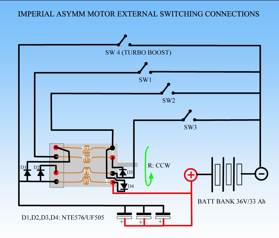
. I have found diodes that will do 20amps and 30 amps. I thought I was going to need much bigger ones, so thats good. I was thinking a bleeder might be bad in this app.
                                In your new vid, the motor is doing about 3500 rpm, which is close to mine. I thought in your original test it was doing 7000 rpm. If you were not pulsing it why was is going so fast. I thoughr it was 36volts straight and thats what I was shooting for

                                @cornboy. That really looks nice. I cant wait to see the finished motor.

                                Comment

                                Working...
                                X