Announcement

Collapse
No announcement yet.

My Motors got me to Tap into Radiant Energy

Collapse
X
 
  • Filter
  • Time
  • Show
Clear All
new posts

  • Hitby13kw
    replied
    Originally posted by prochiro View Post
    Hello All

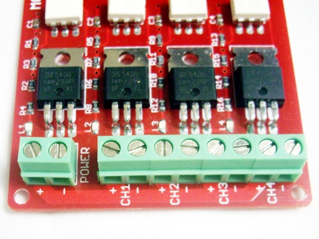
    Some time ago someone posted a picture of a PCB board that had power connectors that were square metal block shaped units with a single screw in the top. They were soldered into the board by four posts. That picture stuck in my mind as maybe the best way to hook up the 12 to 18 volt pulse units we are using. I have looked for that picture and looked thru several sellers of connectors with no luck. Does anyone remember who made that picture or what those type of connectors are called so I can check them out. Better yet where did they come from.

    Dana

    Dana, The quick answer, it was me PM me your address and I can send you a handful - they are setup for a #6 screw
    we will look up the part number tomorrow when I'm awake.

    Hitby13kw

    Leave a comment:


  • Hitby13kw
    replied
    Imperial update

    Originally posted by Ufopolitics View Post
    Hello Guys,

    We have not seen Hitby13kw Set Up working as of yet...but I hope to see it running soon...

    Ufopolitics
    UFO This is for you . . . Many thanks for such a great design,
    This applise to you too John Stone - The Monster Driver is the thing to have !!!


    Batteries Voltage RPM Current draw
    - - 1 - - 12.14 - - 636 - - 0.98 -> 1.09
    - - 2 - - 24.6 - - 1184 - - 1.26 -> 1.56
    - - 3 - - 37.0 - - 1843 - - 1.55 -> 1.70
    - - 4 - - 49.2 - - 2390 - - 1.98 -> 2.28
    - - 5 - - 62.1 - - 3030 - - 2.62 -> 2.92
    - - 6 - - 74.6 - - 3630 - - 2.53 -> 2.69

    In the video we show the motor running a genhead at 3596 RPM pulling 2.69 to 2.94 Amps then with a 100 watt load the RPM dropped to 3555 and the current draw showed 2.79 to 3.02 Amps

    https://www.dropbox.com/s/t5ak1l1au8jwqie/SAM_0208.AVI


    More to come . . .

    Hitby13kw
    -
    Last edited by Hitby13kw; 07-20-2013, 10:59 AM. Reason: video host address change

    Leave a comment:


  • Ufopolitics
    replied
    Attention Please!

    Hello to ALL,

    This is an IMPORTANT ISSUE HERE!

    I received an E-Mail (to my [email protected]) about a very active Member here...Anoop, I don't know if some of you remember Him...But the fact is the following :

    All of the sudden Anoop was not able to Log In into this Forum..??!!

    I will Quote His latest EMail to Me below:

    Hi UFO!

    Thanks very much for your quick reply as usual! I am trying your suggestions for the motors.

    Regarding Energetic Forum, I welcome your offer of assistance. I have not been able to login, nor have I been able to re-register. On the main page there is also no link to any webmaster. And I am unable to send a message to any forum member without logging in! I tried sending a message to Aaron via facebook, but no response. Possibly he did not receive or see the message.
    If you could just forward this message for me to Aaron or any webperson in charge, that would be great. This situation has existed for many months now, but I have meanwhile been quietly following your thread. Luckily I still remembered your easy gmail address!

    Best wishes,

    Anoop
    ANOOP VIDEO ON THREE POLES - YouTube


    I wonder how many more Members have gone through same Issues...but never contacted/approach Us...?


    Not good at all guys...Not Good!


    Regards


    Ufopolitics
    Last edited by Ufopolitics; 07-20-2013, 02:07 AM.

    Leave a comment:


  • prochiro
    replied
    Connectors

    Hello All

    Some time ago someone posted a picture of a PCB board that had power connectors that were square metal block shaped units with a single screw in the top. They were soldered into the board by four posts. That picture stuck in my mind as maybe the best way to hook up the 12 to 18 volt pulse units we are using. I have looked for that picture and looked thru several sellers of connectors with no luck. Does anyone remember who made that picture or what those type of connectors are called so I can check them out. Better yet where did they come from.

    Dana

    Leave a comment:


  • JohnStone
    replied
    Low scale power switch

    All of you who do not intend to drive a HD monster motor, our MonsterDriver might be oversized. I still strongly recommend to build it.
    But before you start simplifications by your own please relay to lower grade circuits with known working performance. Those circuits shall be known in an active community where you can get help and advice. And preferrably they should be commercially available.
    Example: 100V max (quite low!!) and 28 amps continuously (with cooling) add overvoltage protection and heat sink!!!!!!!!
    (IRFD540)


    There you can play with FOD3180 if you want. It will get better performance but you shall know how to do it.

    I recomend this alterntive in order to prevent you from juggling with all free parameters at same time and eternally. Steve Jobs was proud as well of all things he did NOT. The message is: eliminate first as many free moving parameters as possible. DECIDE and hit posts in the ground in order to prevent you from juggling these parameterss again. Then start shaping your setup like an artist.
    If you decide juggling again then decide for another play ground. Michelangelo's David and Mona Lisa will never give a good monolitic artwork.

    BTW: For serious semi commercial applications we will very probaly use ready made power modules in SiC technology. Current data: 1200V, 100A, 80kHz, -40...C. Many manufacturers rush in this direction. Constantly there are new modules with higher performance on market. But that is the concern of tomorrw only when we get such modules for some bucks only.

    Summed up: Let's struggle for anybody getting the monster running. We do not get late for anything.
    JS
    Last edited by JohnStone; 07-18-2013, 02:21 PM.

    Leave a comment:


  • Ufopolitics
    replied
    Hello Guys...

    Hello Guys,

    There are "things" I really can not "get" to understand...

    If We are to be making/building/fabricating this Quad Pulser AS PER John Stone has designed, ..as He has invested so much time into it/Knowing His Expertise on this Fields...having in mind all the Family Issues He is going through...BASED, AS PER What I have shown in my very previous designs...

    If Prochiro (Dana) has shown on videos that amperage gets to be reduced in quite some considerable amounts...without sacrificing Torque or Speed...

    Then why...BEFORE GETTING TO THE VERY END of this Set Up TESTING...We are trying to Modify it, Reduce "space"/Compact it...beyond the Spec's of its Creator...John Stone??

    I would understand to try to "Smooth or Improve" Operations...by Enhancement of Superior Components...but just to "reduce space" or "minimize time of making it"?!

    The fact that Machine Alive's Set Up is not working...is obviously due to some error...but, it has been proven, it definitively makes motor run/turn as per Dana's videos...

    We have not seen Hitby13kw Set Up working as of yet...but I hope to see it running soon...

    I already have the Arduino, and I will order all parts required sometime this week...I will be testing ALL this Set Up soon, as all of you are doing a great work on this...so we could be "working together again".

    We MUST EXHAUST FIRST, all the ORIGINAL SET UP, before going around making changes, on anything else...or we will never reach anything...

    Jumping from point to point without finishing what We started originally is NOT a Scientific Method...we may "hit" it by mistake...but not based on a correct Developing method...as it could take 20 years in the "trying"...

    Like JS wrote above...We are not trying to make "Cosmetic Touches" here...We are not trying to reduce costs to make it "available" to all levels...NOT YET, NOT NOW...We MUST FIRST CONCLUDE "WRITING THIS SONG"...before we start PLAYING IT...MUCH LESS...promoting it to SELL it...

    There will be time for all that...later on...when WE ALL have a "Guiding MAIN Pattern" THAT WORKS...to follow...to change, to modify...in order to "Enhance"


    We CAN NOT "Enhance" something that we do not know if or not is gonna work...

    And...IF IT DOES NOT WORK...Then we will look for other "Alternatives" or Completely NEW Designs...

    So, please guys...let's FOCUS on ONLY ONE THING...BY NOW.


    Let's NOT CHANGE ANY ORIGINAL COMPONENTS...Let's NOT ADD ANY MORE COMPONENTS TO THIS SET UP...

    The Software Codes?

    Yes, the Codes we could play with them...THAT'S DIFFERENT...since it is all about "Commands/Execution" codes...could be enhanced...for proper and better performance...

    BUT, ONLY, WHEN THE PRIMARY CODES ALREADY RUN OUR MOTORS FINE AND "DANDY"...


    If We do not FOLLOW ALL, an ORGANIZED AND "UNIQUE" SCHEDULED/PATH of Events...We will be running in circles...My Friends.


    Regards to All


    Ufopolitics
    Last edited by Ufopolitics; 07-18-2013, 03:41 AM.

    Leave a comment:


  • machinealive
    replied
    Hi guys

    Just got home. No, I'm not using the fod3180. I'll be heading out to the shop soon to see what new 20 ohm do.

    Leave a comment:


  • prochiro
    replied
    Hell JohnStone
    Thanks for reminding me why we duplicated the voltage regulator area. I was just thinking things thru in my head to see if condensing SIZE of board could be condensed some. I am not in any way going to risk the integrity of the design and or function for cost reasons. I trust what you say and will keep further boards complete with four sets of regulators.
    Hitby suggested the FOD3180 and I have already checked it out by reading datasheet and review of previous thread comments. I rejected it almost immediately and also sent PM to Machine asking if he was using the FOD3180 and that it may be his problem also if he was. I have not heard from him yet as he works so late in the day.
    Last edited by prochiro; 07-17-2013, 11:52 PM. Reason: spelling

    Leave a comment:


  • JohnStone
    replied
    Originally posted by prochiro View Post
    Hello John;
    I believe you were asked this before but can't remember. As the Quad has four 12 volt and four 5 volt systems, is it possible to do it with just one set of regulators as only one would would on at a time. The reason I am asking is I am getting ready to condense the setup in size and was also interested in the possibility of condensing complexity and cost as well if possible. My target overall board size is 25cm square which includes mounting area. It all has to be on that one board. If we share regulators but must add more diodes etc, it might not be the practical thing to do.
    Dana
    Very distinct YES/NO
    @ALL:
    The issue is to have very short wire lenth and excessive driving capacity for FETs. I designed the board in order to have one single channel complete on one board. In case of defects we can repleace it or interchenge them in order to decern defective ones or test them after repair.
    The other issue is to restrict disturbancies to a single channel and prevent others to be derated.
    I strongly recommend to not feed the driver or Arduino from motor power battery. You can feed them from one common socket charger or separate battery.
    And beware from weak grounds -I elaberated on this issue recently.
    The measures above are important for research time in order to get any effects or side effects nice separated. Else we can not study them at all. Later on we can devise plenty of optimizations by testing them against a known working setup. I am not amused at all if optimizing starts before we know what we do. This is specially true for researcher who do not master electronics.
    Anybody is free to do what he wants but it makes me feel sad seeing some of you jamming things together and struggling with the side effects of this jam. I will not stop supporting your setups but you can have it much more easy.

    Some of you act like that strange man who missed his plan to save 1 million bucks. Then he decided to instantlxy start the second million.....

    Imagine how you procede when you puzzle a pic with i.e. 500 parts. You spread the parts apart in order to get the overview and pick the next fitting part out of this spread area. You will not get happy if you jam the parts in a can and operate only the top 20 parts.

    Regarding FODxxxx. I suggested this opto/FET driver in the very beginning when we played with the single coil toy - intro for education. It has an opto at input and a moderate FET driver at output. It was nice to hav such a simple setup with moderate switching speed. If you compare FODxxx with MIC driver you compare a lanky lad with a sumo wrestler. (500mA vs. 8A). The only succes will be getting FETS hot or dead when drivein ghigh amps.
    And it will not help to replace SFH617 only with this guy. It is more costly and you will need to add some additional caps at power pins. Of course you can use it but you should know how to operate it. SFH617 is some cents while FODxxx is some bucks.

    In the end you will spend much more money for reworks and defective parts than spending some cheap 7812 and SFH617 for each channel. It is "centware"!

    If you decide to start with small motors and low amps you can omit the expensive high amp FETs and replace them by smaller and cheaper ones. But please build the rest of driver as posted. All components were well chosen for price and performance. They all do their job for pulse shaping and power on disable...... I.e. drivers will not do a good job if we feed them with poor input signals like SFH617.

    Once again: everybody is his own master but please take in account that I can not post all provisions, thoughs and omitted dangers I put into this design. And I am very eager to find out what your real reasons for bad success are.

    Please do not feel offended. I decided to use some hard words because I feel so sad about your bad success. Our goal is to win the race for the first Watt of free energy and not get an award for smallest or cheapest driver.
    JS
    Last edited by JohnStone; 07-17-2013, 10:22 PM.

    Leave a comment:


  • prochiro
    replied
    Hitby
    I just caught this last post befor going home from work. I looks like I should look up this FOD3180 a bit. Thanks for the hint.
    Dana

    Leave a comment:


  • Hitby13kw
    replied
    driver mod

    Originally posted by prochiro View Post
    Hello John;
    I believe you were asked this before but can't remember. As the Quad has four 12 volt and four 5 volt systems, is it possible to do it with just one set of regulators as only one would would on at a time. The reason I am asking is I am getting ready to condense the setup in size and was also interested in the possibility of condensing complexity and cost as well if possible. My target overall board size is 25cm square which includes mounting area. It all has to be on that one board. If we share regulators but must add more diodes etc, it might not be the practical thing to do.
    Dana

    @prochiro, as to your thoughts on reducing the parts count (this would need the blessings of JS & UFO), still running comparison testing between a JS original and a reconfigured one - but it has worked for me both ways.

    The short version if you replace the MIC4452YN driver chip with either a FOD3120 or FOD3180 chip (so far I favor the 3180) you eliminate the need for the SFH617A-3 opto,the 74HC132N nand gate, the 7805 voltage regulator, D3, R1, R4, R8, & C10, etc..

    Team - We almost have it . . .

    Hity13kw

    Leave a comment:


  • prochiro
    replied
    Hello John;
    I believe you were asked this before but can't remember. As the Quad has four 12 volt and four 5 volt systems, is it possible to do it with just one set of regulators as only one would would on at a time. The reason I am asking is I am getting ready to condense the setup in size and was also interested in the possibility of condensing complexity and cost as well if possible. My target overall board size is 25cm square which includes mounting area. It all has to be on that one board. If we share regulators but must add more diodes etc, it might not be the practical thing to do.
    Dana

    Leave a comment:


  • JohnStone
    replied
    Thanks Dana for your post! At least some few guys understood what I try to teach.

    @ALL:
    SHORT FAT GNDs is essential. Anything else is like having multiple taps feeding water in a clogged sink -> you will get any effects you dislike Remember anytime this pic in your mind!!!!!!!)
    Make GND between motor and Monster short and star like or bus bar. This GND point is the reference for all measurement or other electronics and NOT the batterey GND pole.
    The lead to battery can be about a foot but fat. But then it is no GND reference point.
    I strongly recommend to feed the Monster - while researching - separately by a battery or socket charger.
    I showed pics with bus bar and pics with short fat star wiring! SAME length any segment!


    If you omit these hints it is like driving a car without tires - on rims only!!!! Negotiate fun, success and danger!
    JS

    Leave a comment:


  • prochiro
    replied
    Hello UFO
    The newest version is using pulse in pulse so to speak. It is a fixed 490Hz with variable duty cycle. As you know the previous version is fixed frequency at 30Kz and the version before that had all variable. I have versions of all three running all my motors. The smoothest and least amps is the latest one with pulse in pulse. All versions give total voltage at top end. I do not believe the problem Machine has is in the type of pulse. I have duplicated his symptoms by choking voltage through the monster and I hear the same high frequency squeal when only 5.75 volts can get through to fets. He just made a new fet board and has had that symptom since then. I am waiting to-nite when he gets home and we hopefully will find the cause. If not I am going to make a full one piece four banger and send it to him. I am short of fets but we need to have his Imperial running yesterday.
    I mean no disrespect to you but this circuit will run even larger motors than the Imperial. People are not listening to JS or myself about its construction. JS has heavy gauge soldered thru multi-stranded wire soldered directly to the fets. I have not seen this being done. I think the reason my circuit works without issue of fets is I am not choking it anywhere. I have also seen fets with no heat sinks. I have found and reported before that any heat at a fet, even five degrees, is bad news and will cause a chain reaction in all others. I also wonder if everyone is using heat sinking surgical clamps when soldering in all components and especially the fets. It is most likely the fets were distressed while putting them in the board. They will check good at first but fail within a minute. There are as you know many of us trying to get Machine going.

    @ All

    If anyone else is using the monster on an Imperial, it would be nice to see pistures close up so we can all see versions of the detail. Has anyone had success with monster and imperial with a regular PCB without really beefing it up?
    This monster is not just any old Radio Shack Toy, it is a Monster and Mine is built like it was a welder. I had fets blowing every day until I made one that had enough solder on it to weigh a pound.


    Dana

    Leave a comment:


  • machinealive
    replied
    Hey UFO

    I'm right here.

    Actually I'm just getting ready to head on home. First, I use a 15 v@ 1500 ma socket charger for drivers, I get a nice 12 v signal at gates.

    So, in the last video, in the first test, I used the single pulse program. I started at about 50 Hz. The frequency is adjustable.
    In the rest of video, I use the multi-pulse. Frequency is not adjustable. What I have is a main pulse which is less then 10 Hz, the sub pulse is about 300 Hz. These pulse frequencies are not adjustable. I showed were I turn up duty, until sub-pulse is 100 % duty, we get a nice square wave, which is the main pulse. The frequency, drops to less then 10 Hz, from app. 300 Hz.

    Btw, thanks for idea, Garry, and Dana for program. That's quite a difference in operation.

    Before I get home I will say that I feel it is also gate oscillations that are the problems. Watch the last part of video, where there are no neons. The gate oscillations are non stop( so yes, i think frequency is too high). That's what I wanted to show. I never went past 3 ohms previously, and after reading John's post on other thread, I am thinking that may be problem. Anyway, I will be putting on the 20 ohms, asap, might get to start tonight. If you didn't notice, look at the difference gate oscillations, with and without the neons.

    And you noticed the sound is definitely different from last driver. It does sound like when a coil is pulsed too high.

    Later
    Machine

    Leave a comment:

Working...
X