This forum is preserved as a permanent archive. The community continues at eMedia Press.

Announcement

Collapse
No announcement yet.

Muller generator replication by Romerouk

Collapse
X
 
  • Filter
  • Time
  • Show
Clear All
new posts

  • AetherScientist
    replied
    Similarities between Faraday Homopolar and Muller

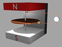
    I have found some similarities with other systems. This time about the conection about Faraday homopolar generator and Muller dynamo.

    About the power generator coil, it's a little similar to Faraday. In faraday generator (modifications have proven to produce COP>1) a copper disk is speeded up and you need to submerge the disk into a magnetic field. Then, you can measure DC, one polarity is in the rotating axis and the other is in the circumference of the metallic disc.

    The difference is in Muller you get the energy directly from the magnet (not from the axis-disc) and you have a coil in the magnet also (in faraday you don't need a coil in the magnet).


    Uploaded with ImageShack.us

    It's well know that there are different transformers where you can use only 1 time-varying electric field in the primary and you get 2 wires in the secondary, other option is to use 2 wires in the primary and instead of using 2 wires in the secondary, you can use a capacitor, or other techniques to get the output.
    Last edited by AetherScientist; 09-10-2011, 10:48 AM.

    Leave a comment:


  • Farmhand
    replied
    Ok call me crazy, but has anyone entertained the idea of using an outrunner like rod has, and using that to spin up the Muller rotor with gen coils and a couple of drive coils, to many rpm ( really fast ) then when the speed up happens engage the drive coils to keep it spinning and switch the out runner from power to generate.

    Some gen coils could be high impedance speed-up one's and some gen coils for current. This way in high speed mode the accelerator gen coils and the pulse/drive coils would spin the rotor and the current gen coils and the outrunner could power loads. Maybe. The pulse drive coils being on the outside would have some leverage to work with against the outrunner as would the accelerator gen coils. Possibly the speed could be controlled by the pulse drive coils a bit.

    Anyway I just thought I would ask if anyone has thought along those lines.

    On a side note I'm surprised to see how much power it require's to run most appliances with motors. No wonder there is an energy crisis. 750 watts for a blender. I think i'll use the knife more.

    Cheers

    Leave a comment:


  • nvisser
    replied
    Originally posted by toranarod View Post
    just for curiosity I still have one of theses in the shed.
    it's the project I put on the back burner. Maybe time to get it out.
    this is the fisher & Paykel washing machine, called the smart drive.
    Hi Toranarod
    You might find this interesting. They show you how to make a generator out of this motors.
    Helical Wind Turbine PDF File | Docs Library

    Vissie

    Leave a comment:


  • Shadesz
    replied
    Angled core face idea

    Here is the idea I was talking about. Simply stated we angle the core face so as to add a sideways force to the rotor. There is a lot to this so please read the description.


    When using a high permeable core I believe this will allow us to minimize some lenz drag as the magnet approaches the rotor. (the magnet is attracted to the pickup point of the core, vs the copper coil)

    You will also notice that I placed the magnets where they will have a neutral side to side force. I think this is very important.

    I feel the second design has more potential because of where this 'neutral' point is located. Notice that it is off center from the coil (after the coil). We can use that I think.

    Also notice... with a properly designed assymetric generator, all but one of your coil (sets) will be propelling the rotor forward. I wonder if the forward propulsion is enough to overcome the cogg from the one coil. Can you say free forward motion anyone? If not that is ok, every bit of efficiency we can design into one of these generators the better.

    And lastly, the core will not saturate so abruptly (it will charge based on the relation of the distance of the magnet to the core). This gradual charge will cause the output energy to be more of a wave than a spike. Not sure if we want that in these systems, I just suspect that it is an inherent result of this core design. Do you think a more gradual wave is a good thing to have here?

    Last edit: here is a link to the thread I created to help us calculate this sideways force...
    Last edited by Shadesz; 09-10-2011, 11:09 AM.

    Leave a comment:


  • Shadesz
    replied
    Originally posted by elias View Post
    Hi Rod!

    Glad to see you again. Transformer cores come with an I and a U, you can use the U part for this type of coil. But I think that the most valuable effect that we have seen is the one with your Adams type generator, we need to replicate this.

    This is how I think it might have worked: Magnetic fields repel much strongly perpendicularly. You can try pulling two attached magnets apart to see what I mean, but if you slide them over they are much easily taken apart. In the Adams type generator the outward force is also utilized to some degree, adding to the overall efficiency.
    I'm not quit following here. Can you show us a picture of what you mean?

    BTW: Did you mention deforming the core head, so that this effect manifests much better? I did not understand this part.

    Elias
    I mentioned to Rod in an E-mail some ideas I had. I think deforming the core head is a good idea. See this thread I started to try to picture it better.


    If someone can help us figure out how to calculate the sideways pull force, I will put together a spreadsheet that will let us figure out the best core size, angle, and distance from the rotor magnets, etc.

    If you think about it and design it just right, on a generator with say 8 coil (sets) and 9 magnets... 7 cores will be propelling the rotor forward while only one will be "cogging" I wonder if the sideways pull force from the 7 would be enough to overpower the cogging force from the one. If it is, whammo, a rotor drive without any input. (although I doubt it would get to a significant speed)

    Hence I want to find the way to calculate pull force. I want to at least minimize the cogging force, or maybe even better.

    I have some other out of the box ideas that I think you guys will be interested in. Man my itch to build a unit is growing so badly! lol.
    Last edited by Shadesz; 09-10-2011, 09:29 AM.

    Leave a comment:


  • Shadesz
    replied
    Interesting idea. Good job. Let us know how it turns out.


    Originally posted by Farmhand View Post
    Microwave oven fan that I have could be easily cut to make that I think.
    They even have a fine wire coil on them but maybe no good. The fan motor looks a bit Tesla-ish. Oh it's laminated steel I think.

    I'll post a picture as soon as possible.

    Edit: this is the Fan motor it's fairly big. The coil is 30mm long and it's 60 mm to the topside of the rotor/core. There's about 12.5 mm's of lamination thickness.


    Uploaded with ImageShack.us


    Uploaded with ImageShack.us

    Cheers

    Leave a comment:


  • Shadesz
    replied
    Originally posted by kajunkreations View Post
    @ shadez..

    yes, 1" neos and 1" cores, the mix was 70/30, like a paste,very difficult to fill the mold. the mesh is 350, very fine. It is possible that it was too thick, i was thinking that as i made them. I want to get a few opinions and try again.
    Thanks for the information. Good luck

    Leave a comment:


  • toranarod
    replied
    Originally posted by AetherScientist View Post
    It looks like a faraday homopolar generator. It's not the same, but it has some similarity.

    That gives it a good chance at providing useful Data. Well worth setup.

    Leave a comment:


  • toranarod
    replied
    just for curiosity I still have one of theses in the shed.
    it's the project I put on the back burner. Maybe time to get it out.


    this is the fisher & Paykel washing machine, called the smart drive.
    Last edited by toranarod; 09-10-2011, 08:48 AM.

    Leave a comment:


  • AetherScientist
    replied
    Originally posted by toranarod View Post


    I like this coil arrangement.

    do you have any more specification on this idea. I have a few old TV EHT Ferris former's that would do for this. But I am not in favor of ferrite.
    It looks like a faraday homopolar generator. It's not the same, but it has some similarity.

    Leave a comment:


  • toranarod
    replied
    Originally posted by Farmhand View Post
    Microwave oven fan that I have could be easily cut to make that I think.
    They even have a fine wire coil on them but maybe no good. The fan motor looks a bit Tesla-ish. Oh it's laminated steel I think.

    I'll post a picture as soon as possible.

    Edit: this is the Fan motor it's fairly big. The coil is 30mm long and it's 60 mm to the topside of the rotor/core. There's about 12.5 mm's of lamination thickness.


    Uploaded with ImageShack.us


    Uploaded with ImageShack.us

    Cheers
    Ok. I am going straight out side to my Micro wave oven. I had never thought the fan was going to be useful. I kept it for the diodes and Magnetron.

    Somtimes I just dont have an imagination. I was repering the dishwasher the other day and I was replacing the drain pump. Same Motor? Went in the bin.

    on my Adams motor I need to install another out runner. they are great for control over a wide range Of RPM.

    I turned things around today and went back to smaller magnets that gives you more space between the phases . as in the photo presented by marxist


    dead short and open circuit had the same RPM. I was testing the large 50mm coil with the 24mm core same as above. Smaller magnets, 10mm X 10mm
    Last edited by toranarod; 09-10-2011, 08:40 AM.

    Leave a comment:


  • elias
    replied
    Hi Rod!

    Glad to see you again. Transformer cores come with an I and a U, you can use the U part for this type of coil. But I think that the most valuable effect that we have seen is the one with your Adams type generator, we need to replicate this.

    This is how I think it might have worked: Magnetic fields repel much strongly perpendicularly. You can try pulling two attached magnets apart to see what I mean, but if you slide them over they are much easily taken apart. In the Adams type generator the outward force is also utilized to some degree, adding to the overall efficiency.

    BTW: Did you mention deforming the core head, so that this effect manifests much better? I did not understand this part.

    Elias

    Originally posted by toranarod View Post


    I like this coil arrangement.

    do you have any more specification on this idea. I have a few old TV EHT Ferris former's that would do for this. But I am not in favor of ferrite.

    Leave a comment:


  • Farmhand
    replied
    Originally posted by toranarod View Post


    I like this coil arrangement.

    do you have any more specification on this idea. I have a few old TV EHT Ferris former's that would do for this. But I am not in favor of ferrite.
    Microwave oven fan that I have could be easily cut to make that I think.
    They even have a fine wire coil on them but maybe no good. The fan motor looks a bit Tesla-ish. Oh it's laminated steel I think.

    I'll post a picture as soon as possible.

    Edit: this is the Fan motor it's fairly big. The coil is 30mm long and it's 60 mm to the topside of the rotor/core. There's about 12.5 mm's of lamination thickness.


    Uploaded with ImageShack.us


    Uploaded with ImageShack.us

    Cheers
    Last edited by Farmhand; 09-10-2011, 04:36 AM.

    Leave a comment:


  • kajunkreations
    replied
    Originally posted by toranarod View Post
    have you put the core in the Motor?
    looks impressive.
    Are you asking if I have used it as a drive coil? If so, then no i have not, just held to the rotor of my romero build . I dont have mosfets that can handle that kind of current yet.

    Leave a comment:


  • toranarod
    replied
    Originally posted by kajunkreations View Post
    @ shadez..

    yes, 1" neos and 1" cores, the mix was 70/30, like a paste,very difficult to fill the mold. the mesh is 350, very fine. It is possible that it was too thick, i was thinking that as i made them. I want to get a few opinions and try again.
    have you put the core in the Motor?
    looks impressive.

    Leave a comment:

Working...
X