If this is your first visit, be sure to
check out the FAQ by clicking the
link above. You may have to register
before you can post: click the register link above to proceed. To start viewing messages,
select the forum that you want to visit from the selection below.
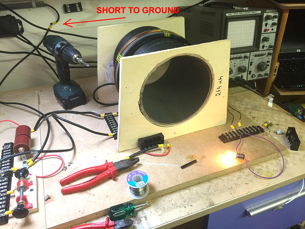
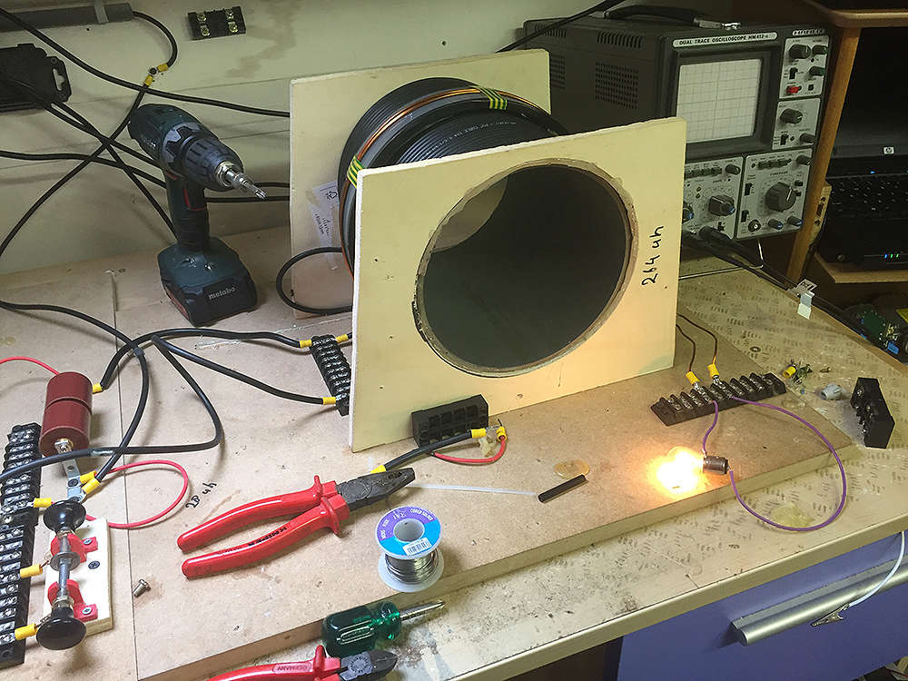
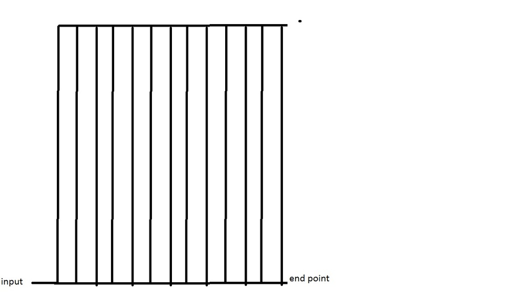
Try to rewind the L1 with high voltage wire. While changing coils i noticed with the magnet wire coil more static everywhere in the room. This is because of shorts in the coil / corona discharge.
I could be you are losing "power".
Shorts too ground will have a similar effect. You can hear it an feel it
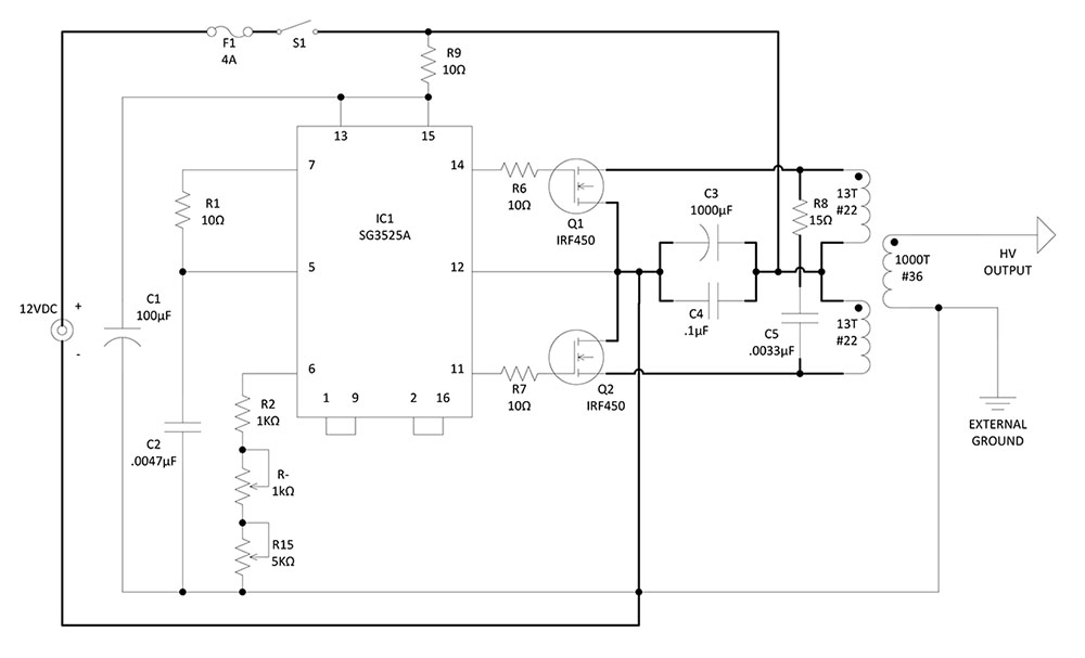
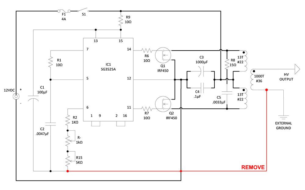
Hmmm, the PVM12 unit I have has two separate "ground" leads, one for the control logic and one at the base of the HV transformer. So it should already be isolated but I haven't verified that it actually is, there could be an internal jumper wire or something. I know this is important, a while back in the thread I mentioned to Tesluh how certain inverters had the output isolated but most had a common ground and this would not work. That little 140W Radio Shack inverter Don used on many of his projects was isolated, I know because I have one I bought years ago. It barely works any more but it's the exact same model and I tested it. I will double check the PVM12 to make sure it's isolated.
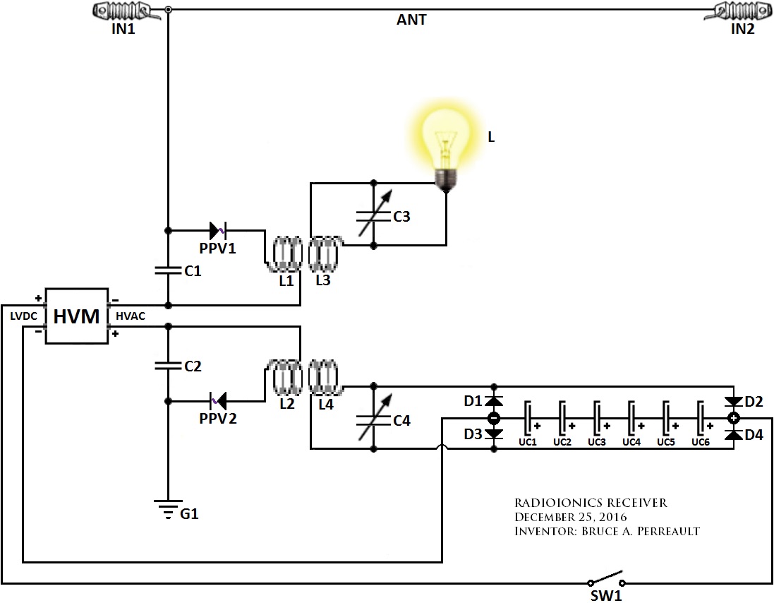
It would appear by the above diagram that the connection of C1 (-) through L1 would make the plate on C2 connection to L1 positive. The C2 plate connected on the PPV side would then become negative. Since the PPV is directional it cannot discharge C2. Possibly reversing PPV1 would solve this which brings into question the polarity on the antenna line... seems like a bit of conflict there...
Moving C2 in line with the antenna where PPV1 is currently located and PPV1 in place of C2 - remove C1 completely and only add the neg HV line from the HVM on the ground side of C2. This would bring it back to a basic Tesla radiant system with the HVM enhanced ground.
Just an observation...
This will work but here is a better circuit!
Merry Christmas!
Without the mirror circuit at least half of the energy spills and goes back into the great void!
I left a charged set of capacitors laying out near a marker. went to reach for the marker and apparently got close enough to discharge them through my bare hand. highly not recommended. going to be more careful about discharging capacitors before touching any part of this circuit!
Thank you Gedfire for the detailed post, now I see the bridge rectifier under that plate coming from the plasma ball. going to tinker some more with that circuit and see if I cant make it do something impressive.
You are welcome Tesluh, all the very best with your research.
Ah and yes I have handled capacitors at a very bad and dangerous time too.
Now its rubber or leather gloves and sometimes rubber water boots on 5 inches of newspaper with a chicken stick depending on what I am doing.
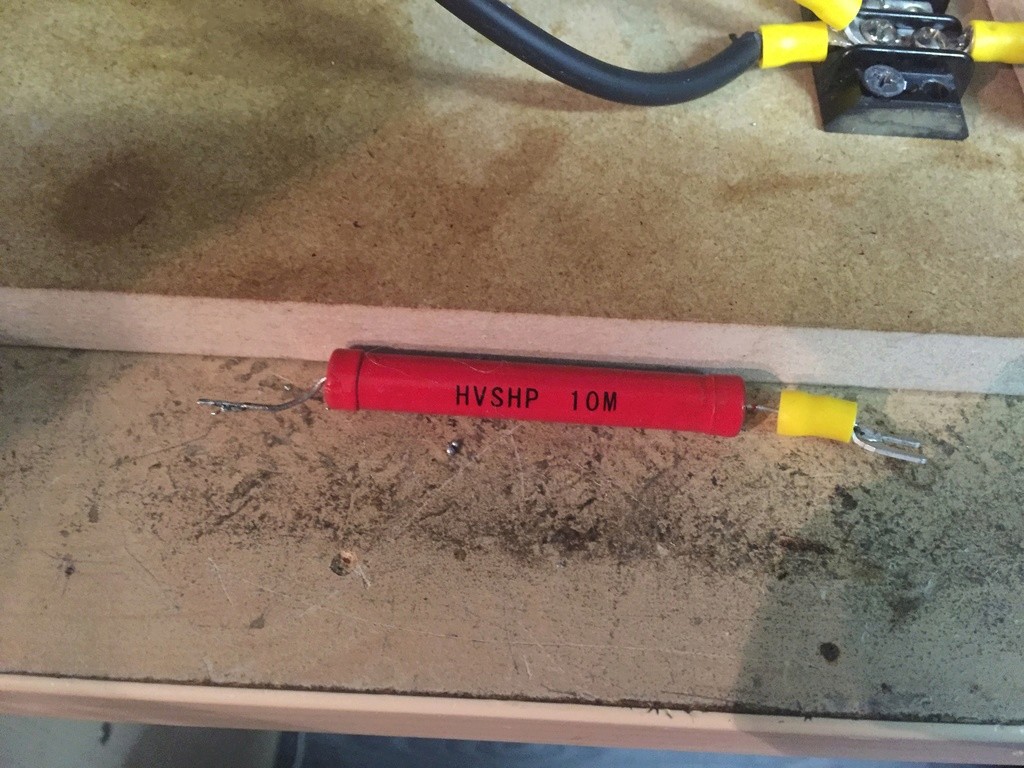
I plug out and discharge my caps at all times. A certain value resistor can be soldered across the terminals to give a slow bleedout of energy over a certain time.Some caps have built in resisitors .Someone else could help you on that or google how to choose a resistor for caps of certain capacity.
I take nothing as granted with caps or electricity related devices these days.Be careful.
Thanks tswift, Thanks dragon, this is very helpful especially the equation , in fact i need a radio frequency train of pulse of high current in order to generate a high magnetic field with less power, the resonance is one solution but how much train of pulse i can generate in my circuit is the problem .. for example 20 KHZ frequency where the current in each pulse is high , the amount of power needed to do this can be very high in order of several KW !
a perfect resonance in high voltage environment is practically very difficult to achieve without sophisticated hardware ..
i am asking active members here about a way to generate high reactive current by mean of resonance or any suitable way , high voltage discharge using a capacitor and coil across spark gap still generate low electric current , the electric current i need in order of 100 A or more , any suggestions ?
thanks in advance
The current generated in a coil can be found using the formula V(C/L)^0.5 = amps. So if you wanted a 100 amp discharge you could use a coil with an inductance of 100uh and a 1 uf cap charged to 1000 volts. ( 1000 volts * ( 1uf / 100uh ) ^ 0.5 = 100 amps )
This type of discharge is reasonably dangerous ( local electronics and physical ). 90% of Voltage is converted to amperage so the end result would create an activity in the range of a 10,000 watt burst in the above case. The key here is to use a coil that has extremely low resistance and low inductance with a relatively large cap or cap bank.
You can research exploding wire ( vaporizing wire ), coil guns, EMP's or other devices that require huge current pulses.
To generate high currents in a circuit (at least very briefly) shouldn't be hard to do. A high voltage discharge from a cap or cap bank will do it but you must minimize resistance and inductance in the circuit. Short wires, thick wires, and no inductors. With large enough caps you can generate pulses of 10,000A, but your caps had better be pulse-rated and able to handle it or you will destroy them. For moderate voltages you can use "photoflash" caps, which are polarized electrolytics with voltage ratings of usually 200-300V range. They are built with low internal resistance and inductance for fast discharge.
WARNING: large caps charged to high voltages store HIGH ENERGY. Making mistakes like tesluh's mishap can be FATAL. The radiant energy circuits we're working on are charged to high voltages but have tiny nanofarad range capacitances and minimal stored energy. Zapping yourself on one of these will get your attention (as I know all too well from firsthand experience) but isn't really dangerous. Working around high energy pulse capacitors demands a whole different level of precautions.
For some examples of working circuits with high discharge currents google things like "can crusher" and "coilgun". The inductance in the circuit has to be LOW not high to achieve large discharge currents.
i am asking active members here about a way to generate high reactive current by mean of resonance or any suitable way , high voltage discharge using a capacitor and coil across spark gap still generate low electric current , the electric current i need in order of 100 A or more , any suggestions ?
I left a charged set of capacitors laying out near a marker. went to reach for the marker and apparently got close enough to discharge them through my bare hand. highly not recommended. going to be more careful about discharging capacitors before touching any part of this circuit!
Thank you Gedfire for the detailed post, now I see the bridge rectifier under that plate coming from the plasma ball. going to tinker some more with that circuit and see if I cant make it do something impressive.





Leave a comment: