
OK, some progress to report. Now at least I have a spark, but it's minimal like serendipitor reported. If I squeeze down the gap to almost shorting out I can get maybe 2-3 sparks per second. It doesn't seem to make much difference how I tune the C2 capacitor but I used the function generator on the workbench to identify the correct position for 500 KHz, so mostly I just left it there.
There seems to be an error in the schematic, the HV diode should be the other way around so that the antenna is charged positive not negative. Dragon noticed the inconsistency and Mwtj also noticed this by reading the text closely and built his device to match the text not the schematic. I flipped the diode and now I have spark, as mentioned above. So far not enough juice to light anything up, but I have several other things to try also.
-
Happy Holidays to you and yours Duncan,Originally posted by Duncan View Post
367 pages ONLY? Aw, we are trying for Edison's light bulb trials record.... Look where that go him! Just jesting.
I enjoyed everything on this thread.I have a great respect and admiration for those who are still perservering in whatever project they are working on. Also the new contributors.
Personally, its my hobby.So to me it was time well spent.This forum expanded my mind like no other. I know I have not made a device that can run a 400w drill yet, but after all these years, I am just getting started...NOW I am understanding more aspects of these energy devices.
Time is the master. I think there are more exciting times ahead... All the best folks!
I am off to get a real cool glass of :
Whatever you can do,or dream you can,begin it.Boldness has genius,power and magic in it.Begin it now. WOW!! Thanks for that reminder Duncan, I got a rush from that.Leave a comment:
-
wow 367 pages is that a record ? - to good to be true ? I bloody well hope not there's a awful lot of effort and years here including a few posts of mine. I still think its there somewhere please keep plugging away guys ! In the mean time I wish you all Merry Christmas.
Leave a comment:
-
Tesluh's replication
Hi Tesluh,Originally posted by tesluh View Post
Try a diode bridge to capacitor.Standard Rectification circuit with smoothing capacitor.
Get a capacitor with high enough voltage.Maybe a GDT @110v or 220v across the cap to limit it to a specific voltage.If so you can make your cap 400 volts.

This Donald Smith's Plasma globe.I suspect that in the second image the diode bridge is present but hidden.From experience,fact checking and anecdotal evidence from Don himself, the wire configuration coming out of the globe goes into a diode bridge and just look at the output wire connections to the output capacitors.
By the way, you get everything, BEMF and all with the diode bridge.Diode bridges were clearly seen on some of Don's Devices:
A schematic:
A 2nd device: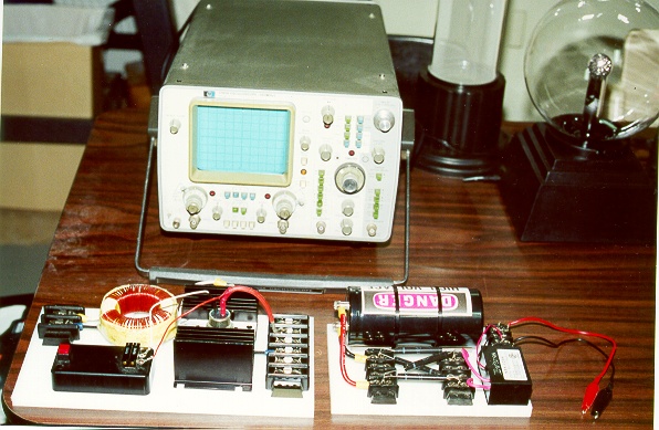
Its very simple really.Nothing mysterious or out of the ordinary.I have tried charging caps with back EMF using two diodes and a diode brigde with capacitor and I was very successful.The bridge is much better.
After outputing to capacitor, the now DC voltage needs to be converted to 50 or 60 Hertz AC or pulsed DC.So a thyristor is used with a frequency generator to pulse the output DC from the capacitor at the desired hertz .Which gives AC on the output or L2 coils via a regular iron core transformer if you wish.
View more at: http://www.energeticforum.com/222882-post8566.html
GedLast edited by Gedfire; 12-23-2016, 03:40 AM.Leave a comment:
-
There are some nice builds shown so far between yourself and Mwtj, nice work guys ! I haven't seen any others if there are any...Originally posted by tswift View Post
I have several projects going right now, pertaining to and leading to one end project, otherwise I could be easily tempted to join in.
As far as the Don Smith and related projects, it's easy enough to build a resonant system to light several 100 watt bulbs fairly efficiently but I've yet to see anything totally self sustaining in this area.
The only thing I've found that is self sustaining is the use of ground currents, although, this type of harvesting requires a number of small circuits to end up with a use-able output, other than lighting.
For the most part I've resigned to working on practical solutions to everyday needs... with the exception of a few side projects that I find interesting.Leave a comment:
-
Using flyback with build in diode. used positive for antenna. negative to ground.Originally posted by soundiceuk View Post
Used the loop antenna and copper ground rod. No antenna no spark.
C1 2 x 60kv 500pf (550 measured) in parallel 1.1nf
C2 110pf with 2x 60kv 500pf in series about between 400 and 500PF
C3 10nf
190uH L1 38 turns. Resonant around 500khz
10.5uH L2 4 turns Magnet 2mm wire. Resonant around 500khz
Needs work to be 100% efficientLast edited by Mwtj; 12-22-2016, 08:07 PM.Leave a comment:
-
From past experience Dragon is a VERY skilled replicator, R&D and all out good fellow!Originally posted by tswift View PostLeave a comment:
-
Mwtj is the first to light up a bulb in open loop.
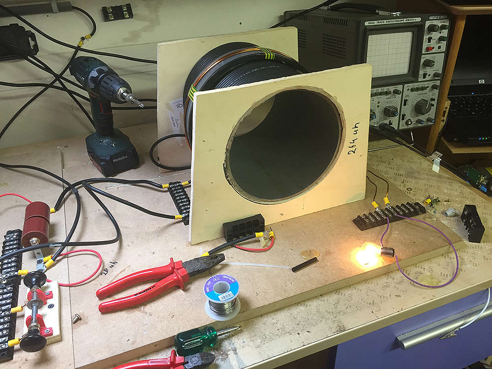
Is the circuit exactly as the diagram?
What component values did you end up using?
I notice you switched to HV wire for L1.
Are you using a loop antenna?Last edited by soundiceuk; 12-22-2016, 06:21 PM.Leave a comment:
-
Dragon, good to see you here! I read many of your posts from the earlier pages of this thread, a lot of the action happened before I showed up but I have read it all through, twice. I know you were around in the Zilano days, how far did you get with your own experimentation?
For me and the other replicators, we are just going by the instructions we have so far. The design looks promising enough that I'm committing my own funds and time hoping it pans out. I don't want to depart from the design as given yet, but if I am unable to produce results after a long time experimenting then I may have no choice. Early results from some of the other replicators look promising so I am still optimistic that this design works as advertised.Leave a comment:
-
It would appear by the above diagram that the connection of C1 (-) through L1 would make the plate on C2 connection to L1 positive. The C2 plate connected on the PPV side would then become negative. Since the PPV is directional it cannot discharge C2. Possibly reversing PPV1 would solve this which brings into question the polarity on the antenna line... seems like a bit of conflict there...
Moving C2 in line with the antenna where PPV1 is currently located and PPV1 in place of C2 - remove C1 completely and only add the neg HV line from the HVM on the ground side of C2. This would bring it back to a basic Tesla radiant system with the HVM enhanced ground.
Just an observation...Leave a comment:
-
I've seen that video before and it is definitely interesting. I don't think this demonstration is necessarily overunity but it does illustrate a principle. The circuit I don't know about, it could be just a pair of diodes in an avramenko configuration. But even if the capacitor acquires a radiant charge you'll never see it by discharging into a resistive load like a light bulb. Now if you run an inverter or a motor from it where Lenz's law is involved, I think you might see some remarkable effects!
I think you're on the right track here tesluh, the same one I've been on. Even more important than reproducing the Don Smith DEVICE is understanding the Don Smith PRINCIPLE, because if we can nail down what is actually happening in Don's devices and why it happens, then reproducing any given device becomes easy. Things like Don's patent application for the dipole generator have some more details that are omitted from some of his later devices, at least the parts he chose to show. For instance, the absolute essentialness of the output transformer or inverter of some kind to convert the radiant energy back to conventional EM with a power gain. Later on in "Radiant Energy Methods", Don just mentions it obliquely with statements such as "amperage only becomes a consideration at the output transformer", which is conveniently never shown on the schematics. This is another clue that it's important, by not showing it Don knew that most people would never be able to build the device successfully.
And yes, the device doesn't look half bad but I want to build a really pretty one in all acrylic. Once I get it working, that is!Leave a comment:
-
great craftsmanship, hope you see results.
Can anyone suggest what the circuit looks like running in this video gedfire posted.
[VIDEO]https://www.youtube.com/watch?v=z-YJ7fdvM1M[/VIDEO]
this seems to be exactly what I am trying to do with the plasma tube and plates, pretty sure it just needs a larger "collector" (higher capacitance capacitor) to be overunity. The plasma tube itself seems to take very little current to operate and it disturbs a large area around it.Leave a comment:
-
Initial Testing
I installed the completed device in its test location, where the antenna terminates. So far no results to report, but I didn't expect instant success. For some reason I'm not getting a spark at all even though the HV is definitely on and working, so I'm double-checking my connections and rechecking the tuning. The picture is of the device installed in my old battery box, where I used to have 8 large deep-cycle batteries for my small solar system, before the batteries went bad.Leave a comment:
-
Tesluh's replication
Congratulations! I agree that its great that you are experimenting. Keep up the good work.Originally posted by tesluh View Post
Inserting the tube into a coil has my interest as I believe Don was suggesting that the terfonal D rod should be the core in the slide out tabletop version you referred to.
AND that the driver would be at self resonance, with the rest of the device.The fields of the coils influencing the switching or pulsong of the NST.Just a theory.
I see a like minded experimenter here: (I had to re upload the first two videos as I could not find them on youtube.What's the language beign spoken?)
Again I say the capacitor plates or mesh in don devices are like antennas in a sense... think about it.Last edited by Gedfire; 12-22-2016, 12:53 AM.Leave a comment:

Leave a comment: