If this is your first visit, be sure to
check out the FAQ by clicking the
link above. You may have to register
before you can post: click the register link above to proceed. To start viewing messages,
select the forum that you want to visit from the selection below.
Here is an antenna design that I purchased plans and tested years ago. Much simpler than stringing lots of wire in the air. At the time, I used a battery between ground and the cap connection to polarize the cap and was able to get 4-10 watts of energy periodically. It would run consistently in the range of 5 to 20 hz with varying degrees of output. Using a 2 in dia tube 8 ft long offers the same surface area as 500 ft of 20 ga wire.
With the HVM it might be enhanced to operate at higher frequencies... the trick might be in the balancing of power required to maintain the HVM and energy harvested by the system. As well, like Tswift is experiencing, controlling the "leaks"
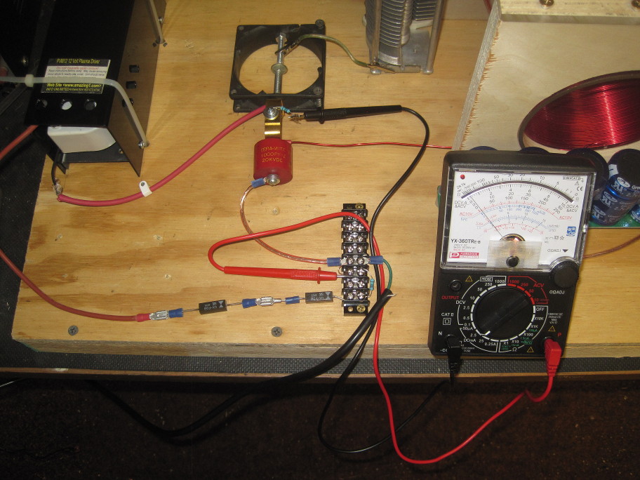
Well, I found at least part of my problem. I finally bought an ANALOG voltmeter, I got tired of frying digital ones. Not that I'm careless with them, but operating close to spark gaps and high voltage oscillating circuits does funny things to them and eventually causes damage. I have a 100M HV rated resistor on order but not in yet, but I do have a few 10M film resistors that can take a couple kilovolts in my parts bin. So I hooked up a resistor and the multimeter to measure current through the resistor. To my surprise, C1 is only charging to around 1,000 volts. It should be much higher, 10KV at least. So somewhere I have a conductive path to ground that's leaking enough current to matter, or else my PVM12 is not operating properly. It does light up fluorescent tubes just fine so it's not obvious what the problem might be. So now I need to do more checking and see if there's a subtle leak somewhere. One of the problem with high voltage projects is that we are often using parts that aren't HV-rated, take the terminal blocks for example. Even with proper insulation on the wires, there can be conductive paths through wood or other materials. Exposed joints are a problem. Any sharp points or small radii can have corona loss. The higher the voltage the worse it gets.
OK, apparently we have an email communications problem somewhere, we'll have to figure that out. But the good news is that my first parcel of HV wire just arrived so I can finish fixing the PVM12 properly. The large parcel with the big spool won't be here until next week. Of course today is New Year's Eve so there are some other activities on the schedule and I probably won't get a chance to do much more today. Happy New Year to everyone!
OK, apparently we have an email communications problem somewhere, we'll have to figure that out. But the good news is that my first parcel of HV wire just arrived so I can finish fixing the PVM12 properly. The large parcel with the big spool won't be here until next week. Of course today is New Year's Eve so there are some other activities on the schedule and I probably won't get a chance to do much more today. Happy New Year to everyone!
Tswift I've been emailing you all day and just got an email saying you haven't had any emails from me.
Bruce never told me to test your antenna this way, I just thought it might be a way to test it so my apologies about that.
I'm certain your fault is just down to polarity of your flyback output leads.
If the polarity of PPV is wrong then it won't work.
This article is relevant and takes me back to my first Crypton Tuning lesson in 1998. For those that don't know it was a Crt oscilloscope mainly designed for measuring primary and secondary ignition systems on vehicles with points, condenser and distributor.
The PPV is similar to the spark plug in the article.
Still actively troubleshooting here, just wanted to give an update. I discovered that not only was my high voltage module (the PVM12) wired differently than I thought, and I hooked it up wrong, but there are several other issues as well. The high voltage diode I'm using is only rated for 8KV, I thought it was 16. There also seems to be a problem with my antenna, just driving the antenna wire directly from the PVM12 HV/HF output, it should be able to light up a fluorescent tube anywhere along the wire and it doesn't. The PVM12 is working, I checked that, but there's enough of a leak to ground somewhere along my antenna to cause problems. I did a visual inspection walking the whole length and nothing is visibly touching it, but at these voltages it doesn't take much. There could be spiderwebs shorting it out or the old PVC pipe I'm using for poles could be slightly conductive. Without a real megohmmeter I have no good way to tell.
I'm also hampered by not having any good way to measure HV voltages. The scope can't read beyond 300V, and the multimeter beyond 1000. I have parts on order to make a kilovolt meter that I can read the actual antenna voltage with, a microammeter plus a 100M high voltage resistor will do it. I also finally ordered a true high voltage 100X 5KV rated scope probe, that will help considerably in troubleshooting. So now I'm waiting on parts yet again....
Just in case anyone thinks it's as simple as throwing a few parts together and expecting it to work right the first time, it isn't. But I have way too much invested in this project, time, money, and large pieces of my life, to turn back now so I'm pressing ahead even though it's getting a bit expensive. Just be prepared that if you want to embark on a build and see it through, there will be some significant cost involved.
Using the sellers information in HV wire 22AWG 0.1" and outside diameter 0.178" I noticed that to keep the inductance of 190uH the amount of turns went up to 43.
So definitely pay attention to those dimensions because the length went up to 1080" with 43 turns.
Of course the length of the coil form goes up too.
So we need near 180ft of hv wire (I had spare for connecting the part.)
I am in Canada and my gps give me an elevation of 883ft. I think it will be ok...
So right now I have :
-Wire for the ant.
-ground rod
-zvs driver + flyback
-c1 and c2
-part for building the 2x PPV
-wire for building L3 - L4
-Fast diode D1- D2- D3- D4
-bunch of small 20f 2,7vdc cap (will use it cause have it on hand...) Maybe a lead/acid battery with a charge controller may also do the job...
will have to order or find:
-30kv or more hv wire for L1 - L2
-8" core for L1 - L2 (I have give a look in an hardware store and 8" is not a common diameter for pvc or abs tube...
-500kohm pot
-2x 250pf 1500v variable air cap C3-C4... I have hard time to find them on the net... and they seem really expensive... maybe I will end by building it...
if someone have a good suggestion on it let me know.
So until I have all the parts, I will follow your works guys!



Leave a comment: