If this is your first visit, be sure to
check out the FAQ by clicking the
link above. You may have to register
before you can post: click the register link above to proceed. To start viewing messages,
select the forum that you want to visit from the selection below.
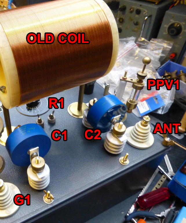
Tuning frequency of the resonant circuit can be done approximately by measuring the capacitance of the capacitor and the inductance of the coil separately with an LC or LCR meter. This won't take into account factors like the parasitic capacitance of the coil so the computed frequency will generally be high compared to an actual measurement. You can measure the actual resonant frequency at low voltage by using a function generator to drive the cap and coil in parallel (through a resistor of 1K-10K), while watching the voltage across the LC tank circuit combo on an oscilloscope. There will be a very noticeable voltage peak at the parallel resonant frequency, but to do this you have to have a scope and a function generator. Even then, I have found that the actual resonant frequency in-circuit while being driven with the spark gap is not always quite identical but it's quite close.
So if you want the $20 solution, you can get a cheap LC meter from ebay. They work OK and will get you in the ballpark. The better answer involves better test equipment and more money. I have been impressed with this Hantek DSO I have, they are reasonably priced and so far it's been quite resilient to damage even working around HV/HF. For regular multimeters I have now gone analog, frying digital meters gets old.
Yes i have some but in the past i have fried meters (digital) when i play with hv/hf... The reading goes like crazy and they just became useless caure they are no longer acurate.
Maybe by having long wire on the low voltage side to get away from the device wile taking mesurement...
I just wonder if you guys have better way to do it cause im not familliar with it.
How do you guys achieve and measure the 500khz?
I suppose it is by varying the gap on the PPV'X' but, in the past, I fried MANY meters on project with spark gap and I need help on the correct way to achieve it...
How much level can the earth ground quality effect an over energy device ? i am doing some experiment where the earth play a critical role , standing waves can be seeing very easily either with a small light bulb or using a scope probes ..
all the test are based on the ETBC but with a ferrite rod inside, the capacitors banks can be charged only when there's an earth ground, now the question arise to how much level will affect the system ?
Hi Soundiceuk and thank you for your quick reply! It is appreciate.
My last question ... ...for today!
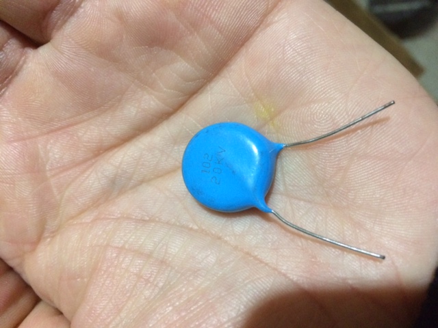
Do the variable air cap really need to be 1,5kv rating?? In the new version (V.7.0.0) they both are on the low voltage side... I don't understand why a 250v will not do the job?
If so it will be another great news cause these are much less expensive and easily found than the 1500v ones.
Thank you guys for the info on the cap. It is good news!
Sorry for that but I have another question... (as I have said before I may have many!! )
It is the second time I see a replication using magnet wire on the hv side. (L1-L2) Do these wire are really enough insulate for that??? If so it is another good news cause I have a bunch of them. For how much volt are they be made for? Maybe using these magnet wire with some spacer between the turn to avoid arcing, I think of something like plastic wire from a grass trimmer...


Leave a comment: