
Originally posted by LowTechIsCool
View Post
-
I tend to use DC output because it's easy to get accurate measurement when you have DC in and DC out. Simple current shunt and volt meter. Simple way to do this is a mechanical connection (belt or direct coupling) from the motor to a GM 10-SI alternator (either permanent magnet or regulated) into a battery bank. Since 746 watts = 1 horsepower we know we have a fairly accurate reading based on that setup. Simply load the alternator down until the motor can no longer hold it's current RPM and take your readings. You already know that there are frictional losses etc with this setup so it's accurate to say that whatever output you get is conservative and includes these losses. -
Energy conversion
Does anyone have a good reference for how the Watt to horse power conversion is determined? As in, what device is used to measure the energy changing forms?
-ChrisLeave a comment:
-
Single coil circuit
So, what do you guys think about the circuit design I came up with? Are there any major problems that jump out at you?
The plan is to switch which one has a gate voltage with a Schmitt trigger controlled by a microcontroller.
-ChrisLeave a comment:
-
Thank you Jetijs, that means a lot.
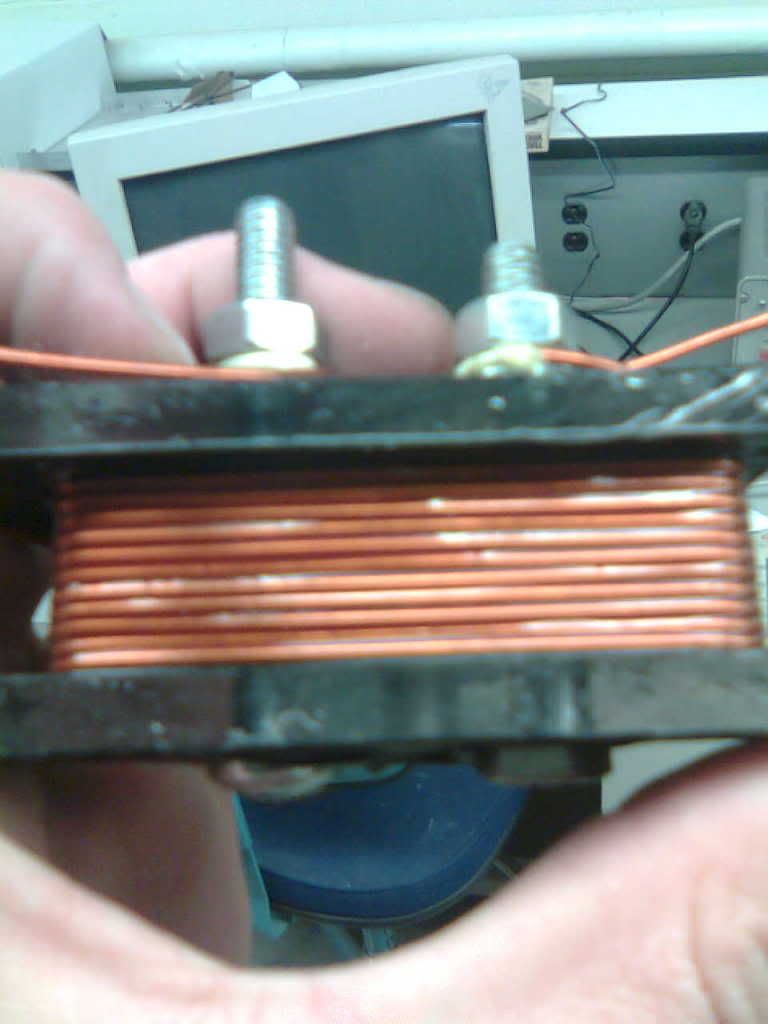
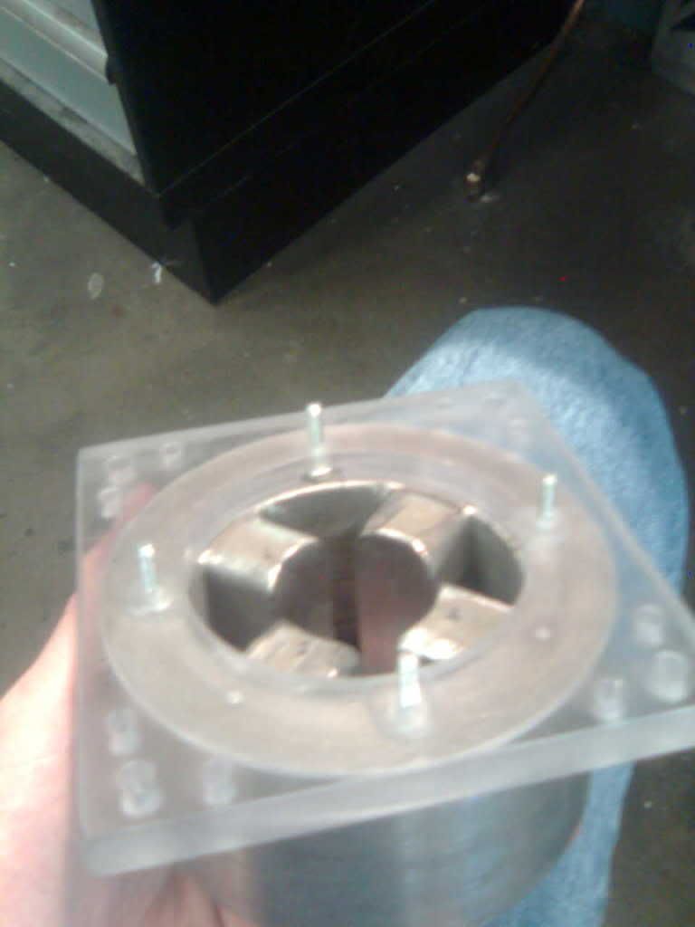
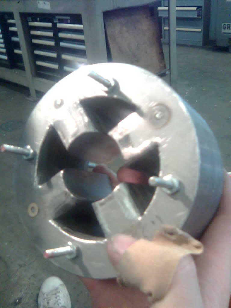
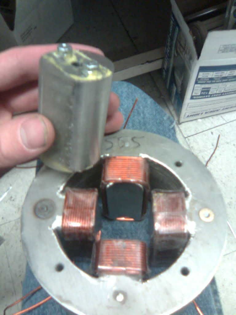
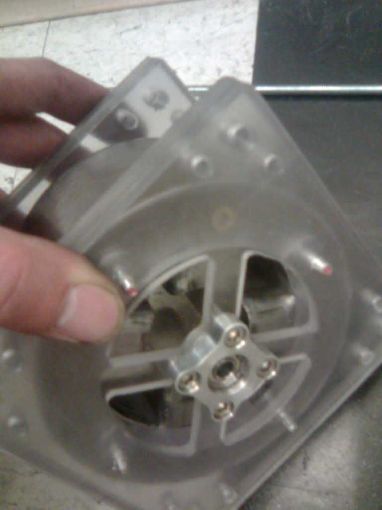
I realized back in December how difficult it is to wind coils by hand, not to mention the poor quality. This lead me to have to stator bored out by a lathe, so that I could fit prewound coils. I could only make enough room to have two layers of coil, down and back. I also learned what the interrupted cut causes, very pretty pattern, but I sanded it off.
I had used a varnish to hold the different layers together, that had its own problems. Do you recommend 'metal epoxy?' Anyway, during the lathing some of the layers came off on the top and bottom of the stator. I epoxied those the layers that came off. This lead to the threaded stock I used in the stator to be stuck, . So I had drill new holes 45 degrees offset.
Leave a comment:
-
You have to use the paper clip icon if you want to attach a picture to your message directly from your computer......
just a thought.......
TjLeave a comment:
-
posting pics
Chris,
I'm not sure why your pics are showing.
When posting a message, make sure to use this icon:
It will then ask for the URL - you can use the one of the pic at wherever you have it posted.Leave a comment:
-
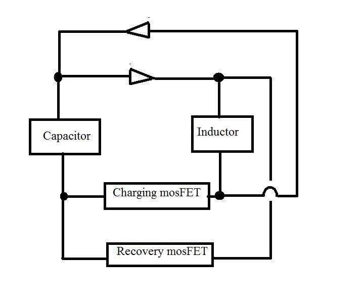
Singel coil recovery
I posted a picture of the circuit I am thinking of. Would this work?Leave a comment:
-
motor pics
Hi,
I know I always like seeing new motor pics posted to the forum, so here are some of mine. I hope the link works.
Leave a comment:
-
more hall tricks ....
I thought this might be hot! This could blow up! But it is an app note from Allegro who makes the halls. I strated using reed switches in glass tubes but they were slow and they seemed to have a latency... I found one with a quick reponse that is potted and encased. But a Hall has the best response.
Here is another try at a solution with a solid State relay.
Comments? Where is the info on this on this board?
-CXLeave a comment:
-
Bedini Seq Bipolar Circuit with Hall trigger...
Here is a Bedini Seq Bipolar circuit with a Hall trigger for an example.....
This schematic is from a page on John's web site.....
TjAttached FilesLeave a comment:
-
-
Circuit design
Hi,
In Jetijs' current setup, he uses a bifilar coil. One of the coils has a diode. The purpose of this is to have two different paths for the current to travel depending on whether you want charging or recovery
Would it be possible to use only one coil and add another diode? I will post a picture of this later today, but it seems to me that two paths could be created and only use one coil.
-Chris CorkumLeave a comment:
-
oh yu can try that circuit but i imagine it will run quite warm and not very good.
yes the resistor bridge is needed to give you very quick clean pulses.
as to the tranny it depends on the size of the motor and now much amps it will want. so far, the only way i ruined some of those particular trannys is by hooking them up wrong but when used with the correct circuit they have never heated up on me.
because i am taking a semi mechanical path i use glass tube reed switches, i have yet to learn much about halls but i imagine that a hall is an npn device so you would need to use a PNP tranny to let it "talk" to another NPN there is more info in previous posts.Last edited by Eric; 05-11-2009, 04:06 PM.Leave a comment:


Leave a comment: