This forum is preserved as a permanent archive. The community continues at eMedia Press.
Announcement

Collapse
No announcement yet.

Electric Motor Secrets

Collapse
X
 
  • Filter
  • Time
  • Show
Clear All
new posts

  • uusedman
    replied
    I am on it, hopefully tonight i can have the measurements for you.

    I am using 22 gauge 110 windings, is that fine? what do you recommend?


    Originally posted by Jetijs View Post
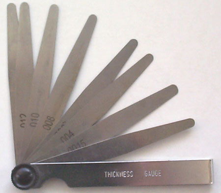
    Use a thickness gauge like this:


    The air gap info would be great

    Leave a comment:


  • Jetijs
    replied
    Use a thickness gauge like this:


    The air gap info would be great
    You say, that the original coils are not enamel coated. Is this right? How did you tell that? Because this does not make sense to me. Or did I misunderstand you?
    Last edited by Jetijs; 04-01-2009, 05:57 PM.

    Leave a comment:


  • uusedman
    replied
    I belive the quality of the video is terrible. Your computer is fine, don't buy another one.

    How do I measure the air gap? (Just be a ruler?)

    Yes, the rotors are odd and they are formed as a slanted "X" shape and not the traditional Cross. I am thinking of using only the smaller shaped rotor. Would I have magnetic flux interfering with the large shaped rotor?


    Originally posted by Jetijs View Post
    looks good
    but what's with the sound? Or is it messed up only on my computer?
    And can you perhaps measure the air gap? Also the rotor poles seem odd.

    Leave a comment:


  • Jetijs
    replied
    looks good
    but what's with the sound? Or is it messed up only on my computer?
    And can you perhaps measure the air gap? Also the rotor poles seem odd.

    Leave a comment:


  • uusedman
    replied
    this is a direct link to the video.

    YouTube - Rotary Attraction 1 1


    Originally posted by uusedman View Post
    It is alive. YouTube - uusedman's Channel. I posted basic modifications of the rotary attraction motor. It is not running 10,000 Rpm, but it is a running and that is a start .

    now, i have to add some other stator and more DC pulse points to get this motor flying.

    Leave a comment:


  • uusedman
    replied
    It is alive. YouTube - uusedman's Channel. I posted basic modifications of the rotary attraction motor. It is not running 10,000 Rpm, but it is a running and that is a start .

    now, i have to add some other stator and more DC pulse points to get this motor flying.

    Leave a comment:


  • LowTechIsCool
    replied
    package in mail

    LOL. Got my switched reluctance motor today too.

    Leave a comment:


  • Jetijs
    replied
    be sure to make a lot of pictures

    Leave a comment:


  • uusedman
    replied
    my switch reluntance motor just arrived. I going to start hacking away. will post something later.

    Leave a comment:


  • lighty
    replied
    Originally posted by LowTechIsCool View Post
    How do the zener diodes placed back to back near the mosFET work?
    Those are not Zener diodes but ultrafast (in the ps) protection diodes (google transil diodes).


    Are you supposed to operate the mosFET in the triode region or in saturation?
    Since MOSFETs are used as switches they must be fully saturated as fast as possible in order to reduce power dissipation and loses of the linear region.

    Leave a comment:


  • LowTechIsCool
    replied
    Good Job

    Jetijs,

    Hooked it up and was able to go 10k+ rpm!!! amazing. It seems to me that a natural application for this would be to hook it up to your Tesla Turbine. Have you designed your devices to connect?

    How do the zener diodes placed back to back near the mosFET work? If you get too much voltage, does it reverse bias and acts as a voltage regulator? Are you supposed to operate the mosFET in the triode region or in saturation?

    With Gratitude,
    Chris Corkum
    Last edited by LowTechIsCool; 03-29-2009, 09:30 PM. Reason: expand on my questioning about an aspect of the schematic I had

    Leave a comment:


  • Jetijs
    replied
    Hi all
    Today I did some experimenting with one of the V3.0 motors. The circuit I used was like this:


    With both phases running, the motor revs up to about 10000 RPM at 12v input voltage. I noticed, that I have my recovery didoes wired wrong so I fixed that, because before there was no recovery at all. At first I attached the output of the recovery to a 40Ah lead acid battery to see if it would climb up. When I started the motor, the battery started to go up, but not as fast as it does with my Bedini selfoscillator at about the same input current. Then I put the recovery to the input capacitor of the circuit board. I noticed, that the motor started to run faster, a bit quieter and the current consumption went down, but just a little - it went down from 6.1A to 5.5A. I expected better results. Then I switched the 1N5408 diodes to UF5408, those are 75nS diodes. This gave no improvement.

    Also I found out that when the motor is running and I am adjusting the timing, as I set the timing for higher speed, the current consumption also increases. So higher speed - more current, but this is only in the timing adjusting phase. If I set the timing solid and the speed increases due to the bearing warm up, the current is going down as the speed increases.

    Another thing about the timing is that the optoswitches have 20uS rise/fall times. This means that I need to adjust the timing at higher speeds to get the optimum timing (max speed). If I use the same (high speed) timing to start the motor, it at first has a little hard time to rev up, but after then it goes smoothly.
    The motor is stable at 11k RPM and vibrates just a tinny little bit. I used four 1n5408 diodes in parallel as the isolation diode for higher current capability (12A) and they get quite hot even if I use just 7A, but I guess that this is not a big problem.

    That's it for now.
    Any comments, suggestions?
    Thanks,
    Jetijs

    Leave a comment:


  • Jetijs
    replied
    And you are doing a great job at it

    Leave a comment:


  • Mark
    replied
    I know, I would expect nothing less. Just giving you a hard time and trying to mess with ya!

    Leave a comment:


  • Jetijs
    replied
    Mark, I want it to be perfect. I have experience with all kind of couplings used on my homemade cnc machines, the lovejoy couplers work best so far. A hose with two clamps is not an option. Also I will take a week off, I need a serious rest for a while
    Thanks,
    Jetijs

    Leave a comment:

Working...
X