
We aren't arguing with what shielding does to the field. We understand that.
As to the rotor on my big machine, listen to the first TEN SECONDS of the video YOU posted in post 372. That will tell you. And if you watch that same video you will see than my 1" magnets have just a bit more than 1" space between them, not 2".
-
Oh I see, so perfecting cancellation is not needed? Humm....?Originally posted by Turion View Post
Let me point out gentlemen that your rotors may slip thru the cracks so to speak because your 1" magnets have 2" spaces between them. The truth is shielding does not subtract any field energy only redirect the energy where needed so as to remove conflicts. Still don't know which rotor in that machine. Hard to judge when the facts are dismal. I am sure it works, not the point of shielding adjustment control.
The shields push the field more out front inside of letting it go wherever.
Leave a comment:
-
bro,
The fuss isn't about the fact that the magnetic field makes it go faster. The fuss is about the fact that all the shielding of the magnets you are doing PROBABLY isn't necessary because something GOOD is happening with the unshielded magnets on both alexelectric's machine and mine. The rotor on the machine in the video and currently on my machine is the rotor with the magnets out at the rim also. But it is a THICKER rotor.
Any rotors on a machine with 12 coils has 12 generator magnets on each side. It also has 12 opposition magnets on each side.
Any rotors for a 10 coil machine only needs 12 magnets on each side.
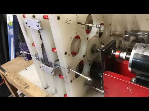
I don't know if I mentioned this, but Greyland reduced the air gap between the rotor and the coils on the machine, and the opposition magnets were no longer able to neutralize the attraction of the rotor magnets to the iron cores of the coils, so he had to move the coil holders back to their original positions. On the final build, we will move them in again to as close as possible, since the gains in output are exponential when you do that, and use thicker opposition magnets, which will give us a stronger repulsion field.
bi,
Those numbers were for my original big machine. I replaced the rotor on that machine with a thicker rotor for a couple reasons. The first reason is that the plastic I was using was 1/2" thick, and when Greyoland drilled holes on each side of the rotor for 1/4" magnets to go in, but left a bit of plastic in between the holes so the magnets would be attracted to each other THROUGH the plastic, the magnets stuck out just a bit on both sides of the rotor. At the time, I didn't think anything of it. The day Peter Lindemann came to see me, I had a rotor magnet that was sticking out hit something at 2800 rpm and the rotor exploded. So changes were required. AND, a thicker rotor doesn't flex as much, so closer tolerances are possible. Because I was going to a thicker rotor ANYWAY, to make sure the magnets would be flush with the rotor surface, I decided to go with thicker magnets (24 1/2' thick magnets instead of 24 1/4" thick magnets, the amp draw went up, so the required input went up. But then again, so SHOULD the output.
So the numbers won't be the same with the machine I have NOW. I haven't measured total output on this machine yet, but I know two coils in series at 2800 rpm were blowing up 300 watt light bulbs, so that's a good sign.
bi, the only reason you have had to wait so long is because you haven't replicated. Easily solved! BroMikey and alexelectric are both seeing everything I have said is possible.Leave a comment:
-
Okay I got is now. Why all the fuss about why it goes faster? No attraction and the repulsion field has to go somewhere. We don't need to write a book on why. No attraction, only repulsion and the repulsion field is energy that must go somewhere so it follows the rotation. This is why people put magnets on the outside ot their factory PMM's. They have been doing that for decades. You add more field energy and it follows the path of least resistance. Come on guys, think
Leave a comment:
-
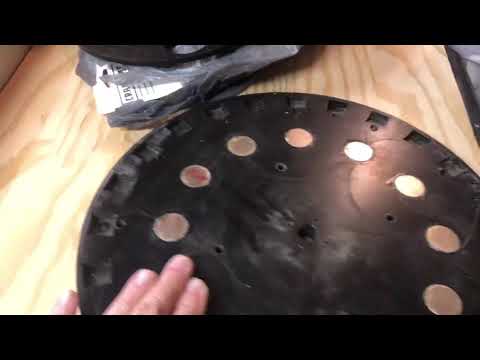
12 magnets on EACH SIDE OF THE ROTOR. That is the way I have been building for years now. The rotor magnets are in pairs. A magnet, a thin piece of the rotor plastic, and then a second magnet. The magnets attract each other through the thin piece of plastic so once you put them IN the rotor, they aren't going to come out. I have talked about this dozens of times in the videos I have made.
"Mr. BroMikey was scared" referred to the fact that when you commented on the video you were worried about how the machine was speeding up like crazy.Leave a comment:
-
Mr. BroMikey was scared?
So now we are talking about the 24 magnet design. That is very important to note
I doubt anyone can explain this. But this is why we experiment, I'll try to find a picture of the right rotor we are discussing, this will help to focus on what reaction is taking place. 12 magnets or 24 magnets will be significantly different.
Originally posted by alexelectric View PostLast edited by BroMikey; 05-04-2020, 02:24 AM.Leave a comment:
-
I finished my downstairs renovation at the old house yesterday, and took the day today to work on getting my shop and storage shed in some kind of order. Stuff has just been hauled down to my workbenches and piled a foot high for several weeks now. Once I clear some space I will be working on getting the 6-5 version of the generator back together. I still have lots to do over at the old house, but the pressure is off a bit, so I can work on some things here at the same time without upsetting my sweetie. That means the generator, and testing the ferrite cores I have been wanting to test.
Alex,
We're seeing the same thing. The rotation of the rotor with the weight of 24 magnets on it out at the rim gives you some "flywheel" effect or action that partially negates the repulsion of the two magnets (rotor magnet and repulsion magnet) when they are coming into alignment and don't WANT to. Once they hit TDC and move slightly beyond, the repulsion effect actually gives some "motor" action as it pushes the rotor magnet away. Because the flywheel effect partially negated the repulsion on the front side, you get a gain on the repulsion on the back side. These two SHOULD have been equal, but the flywheel effect gives you the gain. You may not believe it. Your conditioning may discount it. But I know what we are seeing on the BENCH. And that is way more important than theory or what you were taught in school. Man couldn't fly. The math proved it. Until the Wright brothers did it. The BENCH is the final proof. That's why you HAVE TO BUILD this stuff instead off sitting on your butt spouting textbook crap and worn out theories. I am going to be putting my 6-5 machine black together with ferrite cores in the coils to test them for speed up under load. Once I have done that, I will be contacting Greyland to build a new 6-6 machine for the conference that addresses all the issues we have seen and takes advantage of all we have learned.
Stay tuned.Leave a comment:
-
Turion
You are CORRECT that the magnets attract steel differently than they repel other magnets. But what I am seeing, and what has already been discussed here (alexelectric post 326) is that there is a MAGNETIC assist of some kind going on with these "opposition magnets". It's almost like some half-assed "permanent magnet motor." If you remember, it was freaking Greyland OUT in one of the videos because the motor seemed to be a "runaway" so he refused to operate the machine without some of the coils in it because without them, it was going much faster than it should have for the voltage and amperage he was running it at.
That's correct there is an explanation (alexelectric post 326).
It has an N magnet rotor, facing an N magnet stator as if it were a magnet motor supported by its spin by the DC motor.
So simple that when I saw the configuration it was clear to me the repulsion motor and the CD motor.
In addition to the feature being used for neutralizing magnetic drag, it could be used for other projects.
We are following your progress, Mr. Dave.
Leave a comment:
-
I thought you meant SMALL like a hockey puck. Yeah, those first rotors were a bit scary because the magnets could come out. But if you put TWO of them together with a thin piece of plastic between that the magnets can attract to each other through, they work GREAT. No worries about the magnets coming out at all. Especially if you epoxy the back of them to that thin piece of plasticLeave a comment:

Leave a comment: