Announcement

Collapse
No announcement yet.

ENLIGHTENED MAGNETISM (The Full Proof of Ken Wheeler's Theories)

Collapse
X
 
  • Filter
  • Time
  • Show
Clear All
new posts

  • bistander
    replied
    Originally posted by Ufopolitics View Post
    So, I decided to make a Sensor which Magnetic Field could not be overridden or highly influenced by the magnetic field under observation...like in the video shown previously, those are tiny Rare Earth Magnets, BUT pretty strong. So, the stronger the magnet in your sensor is...the more precise results would be obtained.
    Hi Ufo,

    The sensor strength came to my mind also. I think it is influencing the experiment. The sensor is establishing its own field and distorting the field of the subject object. Sensors for these types of measurements are typically very high impedance devices which have minimal influence on the measurement. You wouldn't happen to have a gaussmeter would you?

    Regards,

    bi

    Leave a comment:


  • bistander
    replied
    Originally posted by Ernst View Post
    Hi Bi,

    You show me the flux pattern of an air core coil. But, ehr... why?
    Originally posted by Ernst View Post
    What would you have expected your sensor to do if the ancient model 1 were correct?
    I know it was a question to Ufo, but I thought it might help, that's all.

    Leave a comment:


  • BroMikey
    replied
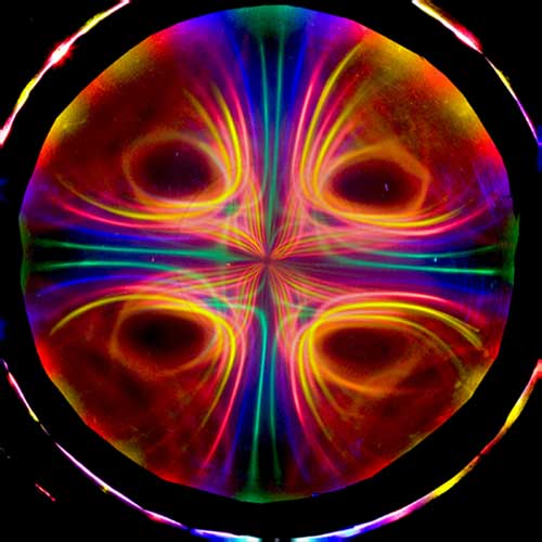
    After watching the video I decided to pull up Ken Wheeler's pretty
    pictures. Then I hacked it so we might focus on the center.

    In Ken's picture we clearly see the same lines of force (MAGNETIC LINES
    OF POWERFUL FORCES) as what UFO has shown with his magnetic tester
    gauge. Nice work UFO. Hat's Off to a thinking man.

    The idea that metal gets magnetized is well known but if heated it will
    resume it's normal status again so I can see where the use of iron filings
    could almost be constituted a trick, especially if ONLY iron filings are
    permitted to measure magnets in schools.

    There I go again, I don't believe anything the US Gov tells me. I have
    figured out almost everything I ever learned all on my own and school
    books often slowed me down in finding the answers.

    It is done by experiment all by your lonesome.

    I see Ken made some of the lines of force other colors. Maybe the
    colors are to keep it from looking all the same?

    But the lines ARE there right where you measured them UFO and
    not one school book has even suggested it once. I think when the US
    gov started flying gravitationally driven crafts around in the 50's
    they decided to keep the public from finding out the root effects
    found in magnets that hold the secrets.

    The green arrows are the lines of force you measured in the video not
    the giant yellow ones.

    Leave a comment:


  • Ernst
    replied
    Hi UFO,
    No matter how much I love miss Universe's waist, if you draw an arbitrary line in a magnetic field, that does not make it a field-line.
    The field lines should always be perpendicular on the gravitational dielectric countervoidance membrane (yes, I am warming up to it , though I have no idea what I am saying) of the small magnets that you have drawn.
    Or in other (normal) words in the N-S direction of those magnets. In the images shown this is clearly not the case, so the "travel flow" with the adorable waist is not a field line.


    Ernst.

    Leave a comment:


  • BroMikey
    replied
    I found some interesting pictures from other schools. Model 1
    is a 6th grade learning tool only. Time to throw away the diapers.
    Yes model 1 is correct in that it has 1 of the patterns present in a
    magnet but our understanding of the more complex
    patterns is emanate.


    Last edited by BroMikey; 12-14-2015, 08:24 AM.

    Leave a comment:


  • Ernst
    replied
    UFO,
    If I had to choose between "OVERWEIGHT BELLY FROM AN OBESE EATING DISORDER PERSON" and "Miss Universe ...90-60-90", Miss Universe would ALWAYS win.

    But my point is that the experiment shown and your graphics support the iron-filings model perfectly.
    You bring it up as evidence against model 1, but it matches perfectly with model 1.


    Ernst.

    Leave a comment:


  • Ufopolitics
    replied
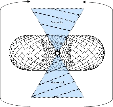
    MORE DEFINED REALITY OF THE TRUE MAGNETIC FIELD SHAPE OF BOTH POLES WITH BISECTORS* AIMING EXACTLY AT JUST ONE (1) POINT, THE CENTER HIGHER PRESSURE FIELD VORTEX[/IMG]

    THE VERY CENTER POSITIONING SENSOR IS DUE TO BEING PULLED BY THE SAME VECTORS OF PULL FORCE PRESENTING ZERO ANGLE (CAN NOT PLEASE AIMING BOTH CENTERS AT THE SAME TIME)

    Ernst, If You would like to start analyzing this in a very critical and specific way...am busy already done it...

    Check Each Sensor Positioning BISECTOR related to exactly the attracting point to both fields.

    Then Compare to Model 1

    And WE have not discussed the INNER CORE RESULTS YET....


    Ufopolitcs
    Last edited by Ufopolitics; 12-14-2015, 08:32 AM.

    Leave a comment:


  • Ernst
    replied
    Hi Bi,

    You show me the flux pattern of an air core coil. But, ehr... why?

    @Ben,
    I was part of that "Dutch disease"...
    But I came out very disillusioned. In response to our protests the Dutch government gave Russia an ultimatum... As if a superpower would respond to a tiny country such as ours!!!
    But Russia DID They actually accepted our proposal!
    So what happened next? Our PM gave this speech:
    "I have hoped and prayed that it would not be necessary, but Russia responded too late..."
    Which was not true, they accepted and they accepted in time.
    But what else could our PM do? The missiles were already installed a few months before the official decision was made.... and even before our protests....

    My faith in our government has never recovered....


    Ernst.

    Leave a comment:


  • Ufopolitics
    replied
    Originally posted by Ernst View Post
    Ok UFO,
    What I have done is....
    - searched for an iron filings image here
    - took your "wrong path" image and scaled it to this image
    - took your "right path" image and scaled it in the same way
    - I flipped the "right path" image vertically so that it appears in the lower half of the image
    - I over-layed the iron filings image with your graphics (sorry for the distortion)

    That image you can find in the attachments to this post.
    What you can see now is that the iron filings do not support your "wrong path" image, but instead match perfectly with the "right path" image.

    So in short, I agree with your graphics, but they do not differentiate between the model 1 and your theory.
    So model 1 is still upheld. No condolences needed .


    Ernst.
    Ernst,

    Take a look at image below:

    [IMG][/IMG]

    The Point to observe here is NOT about a perfect and identical Elliptical Path that always must match,this curves vary with the length of the bar magnet...they become more elongated the longer magnet is...STILL NOT THE MAIN POINT TO OBSERVE

    The Main Point to Observe here is that MODEL 1 does not have a CENTER CONVEX SHAPE, A DEFLECTION INWARDS TOWARDS CENTER EQUATOR, BUT A CONCAVE SHAPE, traveling FURTHER FROM CENTER.

    In reality, the Real Magnetic Field HAVE A VERY SKINNY WAIST, Just like a Miss Universe measurements...90-60-90...While the Model 1 is a FAT, OVERWEIGHT BELLY FROM AN OBESE EATING DISORDER PERSON...


    Understand now?


    Ufopolitics
    Last edited by Ufopolitics; 12-14-2015, 07:54 AM.

    Leave a comment:


  • Ufopolitics
    replied
    Originally posted by bistander View Post
    Hi Ufo,

    Can you repeat with a bar magnet? And with a iron core in the coil?

    Nice experiment Ufo,

    bi
    Sure, Bistander

    I have done it already with almost ANY kind of possibilities...and with strong magnets, the sensor movements are much more radical than on video...actually my PSU as you could notice is not that strong...that coil had 1.0 Ohm and you noticed it dropped to 2.0V...And the coil wire barely got ambient temp.

    I have other experiments which are gonna blow your mind...and exactly by inserting an iron rod inside same coil...


    Ufopolitics

    Leave a comment:


  • Ernst
    replied
    Ok UFO,
    What I have done is....
    - searched for an iron filings image here
    - took your "wrong path" image and scaled it to this image
    - took your "right path" image and scaled it in the same way
    - I flipped the "right path" image vertically so that it appears in the lower half of the image
    - I over-layed the iron filings image with your graphics (sorry for the distortion)

    That image you can find in the attachments to this post.
    What you can see now is that the iron filings do not support your "wrong path" image, but instead match perfectly with the "right path" image.

    So in short, I agree with your graphics, but they do not differentiate between the model 1 and your theory.
    So model 1 is still upheld. No condolences needed .


    Ernst.
    Attached Files

    Leave a comment:


  • Ufopolitics
    replied
    Helping to clear some possible doubts...

    Hello to All,

    It took me quite some time to reach a final conclusion on this whole analysis, and ending building my own magnetic sensor with small BUT strong magnets...

    [IMG][/IMG]

    [IMG][/IMG]

    [IMG][/IMG]

    You will find many, many convincing pictures like the above, based on Iron Filings, showing the fields interlacing as we have known previously in ancient Model 1...However, let's realize that Iron Filings are very LOW FERROMAGNETIC MASS PARTICLES, therefore, when they get influenced by a VERY STRONG MAGNETIC FIELD, they get MAGNETIZED INSTANTANEOUSLY BY INDUCTION, which means they get automatically aligned with the stronger magnetic field poles alignment...

    So, all we are seeing above is just "A FERROMAGNETIC POLARIZED EXTENSION" from that Magnet, JUST LIKE sticking the magnet to a piece of iron, we get an extension of either pole where iron is attached.

    The same exact "Optical Illusion" takes place when very tiny and thin needles from Compasses are moved around a very STRONG MAGNETIC FIELD. Even though needles are magnetized to seek Earth North Pole, the magnetic strength grade is VERY LOW compared to the Magnet being tested. PLUS, the fact that the Compass Arrow displays the false idea that dictates "direction" and not polarization. (see image below)

    [IMG][/IMG]

    So, I decided to make a Sensor which Magnetic Field could not be overridden or highly influenced by the magnetic field under observation...like in the video shown previously, those are tiny Rare Earth Magnets, BUT pretty strong. So, the stronger the magnet in your sensor is...the more precise results would be obtained.

    Regards


    Ufopolitics
    Last edited by Ufopolitics; 12-14-2015, 07:23 AM.

    Leave a comment:


  • bistander
    replied
    Coil field

    Hi Ufo,

    Can you repeat with a bar magnet? And with a iron core in the coil?

    Ernst,

    Conventional theory shows flux pattern like this for an air core coil.


    And here is iron filings flux pattern with a bar magnet and little compasses placed in the field.


    Nice experiment Ufo,

    bi
    Attached Files
    Last edited by bistander; 12-02-2019, 09:45 PM.

    Leave a comment:


  • Ufopolitics
    replied
    Originally posted by Ernst View Post
    Just a quick question about your latest video (great graphics BTW):
    What would you have expected your sensor to do if the ancient model 1 were correct?


    Ernst.
    Thanks Ernst...I am trying to master "the Science of Arts..."...

    That is a great question...however, that is the first Analysis I did in CAD and Animation 3D...following the Wrong Model 1 straight Field Lines Path as "revealed" by iron filings.

    [IMG][/IMG]

    It should have behaved just like above image...Following a straight line BASICALLY when passing A "Non Existing Center Reversal"...so sensor traveling through the shown Travel Path MUST have displaced like shown above, but it did not...

    Instead it behaves like shown on below image...following an aiming inclination towards both end poles

    [IMG][/IMG]

    Compare both "Travel Paths" intervals for both Images, that is where the difference is.

    And finally, the previous image shown again below...where I took sensor as close as possible to coil or magnet center plane to embodiment, and that is when it is noticed the more accurate movement from sensor, describing the round shape of each fields, as always pointing towards extreme end center vortex.(below image)

    [IMG][/IMG]


    Regards


    Ufopolitics
    Last edited by Ufopolitics; 12-14-2015, 06:39 AM.

    Leave a comment:


  • Ernst
    replied
    Just a quick question about your latest video (great graphics BTW):
    What would you have expected your sensor to do if the ancient model 1 were correct?


    Ernst.

    Leave a comment:

Working...
X