This forum is preserved as a permanent archive. The community continues at eMedia Press.

Announcement

Collapse
No announcement yet.

Open discussion for projects on this forum.

Collapse
X
 
  • Filter
  • Time
  • Show
Clear All
new posts

  • boguslaw
    replied
    Originally posted by Farmhand View Post
    Here's m first look at the current through the 0.1 Ohm resistor and the
    voltage of the bad battery or (battery number 3), If I'm not mistaken I see
    current spikes of up to 6 amps with a resulting bump in the battery 3 voltage.

    Three battery test - YouTube

    It stands to reason to me that if the system has reached an equilibrium between
    the motor and the battery 3, "which it does" by splitting the total applied
    voltage of the two supply batteries between the motor and the battery 3,
    then because an equilibrium is already reached then any resulting spikes which
    increase the voltage of the battery 3 suddenly would cause a voltage across
    the motor and battery 3 that is greater than the voltage across the two
    supply batteries, thus causing a reverse emf to the supply and charge them
    momentarily, kinda like a self desulfator circuit does, it takes energy in from
    the supply then with that it produces a reverse emf to be applied to the
    battery. Logic tells me that if the motor and the battery 3 have an equal
    voltage across them to the voltage across the supply batteries, if then all of
    a sudden there is a voltage spike that causes the voltage across the motor
    and battery 3 to exceed the voltage across the two supply batteries current
    will be caused to flow into the supply batteries, this could be thought of as
    reactive power or just a transient reverse emf.

    I still think that is what is happening.

    Cheers
    Farmhand
    I completly agree with your explanation. As I stated on other thread the key factor here is ampere-turns on motor to get the best flyback spike. In fact the whole setup is momentarily the bit DC -DC converter then it formulate the system of two power source opposing themselves with one being of higher potential. And so on, oscillations of slow frequency occur... depending on load across 3 battery.

    Leave a comment:


  • Farmhand
    replied
    Here's m first look at the current through the 0.1 Ohm resistor and the
    voltage of the bad battery or (battery number 3), If I'm not mistaken I see
    current spikes of up to 6 amps with a resulting bump in the battery 3 voltage.

    Three battery test - YouTube

    It stands to reason to me that if the system has reached an equilibrium between
    the motor and the battery 3, "which it does" by splitting the total applied
    voltage of the two supply batteries between the motor and the battery 3,
    then because an equilibrium is already reached then any resulting spikes which
    increase the voltage of the battery 3 suddenly would cause a voltage across
    the motor and battery 3 that is greater than the voltage across the two
    supply batteries, thus causing a reverse emf to the supply and charge them
    momentarily, kinda like a self desulfator circuit does, it takes energy in from
    the supply then with that it produces a reverse emf to be applied to the
    battery. Logic tells me that if the motor and the battery 3 have an equal
    voltage across them to the voltage across the supply batteries, if then all of
    a sudden there is a voltage spike that causes the voltage across the motor
    and battery 3 to exceed the voltage across the two supply batteries current
    will be caused to flow into the supply batteries, this could be thought of as
    reactive power or just a transient reverse emf.

    I still think that is what is happening.

    Cheers

    Leave a comment:


  • Farmhand
    replied
    There's no rush, it will take time for me to think and setup some things to
    experiment with and such. I may be portrayed as an argumentative naysayer
    but I'm not, I just hold my right to an opinion. Like some of the other folks
    on the forums I have some medical issues which mean at times I can do little
    else but think for long periods of time. The main difference between myself and
    the majority of experimenters is time, I have lots of time, but during some
    periods, which could last several weeks, I might only be capable of a few
    hours actual experiment time. Rather than waste the time I am disabled, I
    spend the time on thought by running through setups in my head, sometimes I
    dream I'm building and testing circuits that I'm thinking about because I spend
    so much time just running logic scenario's in my head. I am a firm believer in the saying
    "anyone can do anything anyone else can do, if they want to do it enough".
    Providing the playing field is even.

    People can be very resistant to my theories and evaluations of things, which
    is good, but it makes no sense to me that those same people are so willing to
    accept things that others say when there is no more reason to believe them,
    and in many cases people cannot explain why they believe the claims of
    others, they just do, then reject outright what makes logical sense and can
    be demonstrated.

    There is always plenty of abuse and snide remarks, accusations of being part
    of organised suppression and just plain filthy abuse from the likes of Duncan
    and UFO politics ect. when I or another like me gives an opinion on something
    that they don't agree with, ( this is coercive persuasion ) a form of mind
    control which is very common, it is used on people to try to make them
    conform by making the victim feel as thought if they don't modify their
    behavior they will end up an outcast, it is also a form of suppression because
    it causes people to suppress their own thoughts and opinions and only utter
    what is acceptable. Peer group pressure is a mild form of "coercive persuasion".

    I don't fall for it and I detest it. Some people are quick to abuse and attempt
    ridicule, but when they are proven wrong they often do not apologize for the
    abuse, or simply shut up and let it be forgotten.

    The amount of time I have spent simply defending my right to my opinion and
    battling against people twisting my words ect. is appalling.

    When a people attack the person rather than address the issues it is an
    indication of an attempt to control behavior or thought, (mind control).
    Another tool is hype and catchwords, to bias thought and opinion.

    I won't take it, so they ought be be warned. I control my thoughts and my
    actions. More people need to realize their own potential.

    Argument about the tech is good if it is kept on track.

    I know how to bury a hatchet, I have got a shovel, but it makes no sense to
    bury the hatchet when under sustained attack.

    I don't work well with people who I know detest me, ( i'm not referring to you,
    I have nothing at all against you, I have no reason to ), so I feel more
    comfortable posting here. This way I won't need to waste energy defending
    my dignity. I don't think personal feelings should come into these things.
    When talking tech we need to set emotion aside.

    I'll take my time and try to consider everything.

    Cheers

    Leave a comment:


  • citfta
    replied
    The right "bad" battery

    Hi Farmhand,

    Yes finding the right "dead" battery is the gist of the whole problem. We don't really know why some dead batteries seem to give the effect we are looking for and why some don't. This I think is the main reason Dave started the thread. He was hoping with enough people trying this setup we could figure out what it was about the dead battery that allowed the system to work. Matt realized that on the one system Dave had that was working really well that Dave was using an AGM battery. So that is one big clue. I have found 2 AGM batteries and one of them seems to be working somewhat but not as good as Dave's. The other one seems to be totally dead no matter what I have done to it.

    Several of us have tried to mimic the dead battery with caps and resistors and inductors and anything else we could think of but so far we have not found anything else that would work like the right "dead" battery. Mike Nunnerly has made a suggestion to make a salt battery to replace the dead battery. If I can find some stainless plates I am going to try that and see what happens. I already have plenty of sodium hydroxide from my biodiesel making supplies.

    As far as your measuring of power goes I think that might be useful to help understand what is happening in a working system. I don't think it will mean much to anyone if you don't have a system that is working in the "zone". Getting a system into the "zone" takes some patience which I know you have so I hope you can get the right "dead" battery to see what several of us have seen.

    Good luck,
    Carroll

    PS: Glad to see you trying this. If you get it right I think you will be highly surprised.

    Leave a comment:


  • Farmhand
    replied
    I've made several Edits to the last post.

    Anyway I want to say that I am totally open to discussing the measurement
    protocol, the reasoning behind the theory or whatever else, including
    suggestions to better get the desired effect (which I do understand I might
    not see immediately and may need to tinker to get it to happen).
    This thread is a safe haven for open discussion, so please respect Carroll's
    wishes there.

    I find it convenient that Carroll is familiar with the system and I hope he can
    maybe give suggestion as to how I might produce the desired effect. eg.
    bigger motor, a "modeled bad battery maybe". Or whatever. I want to produce
    the effect so I can study it, but I refuse to ruin any good batteries and my
    stack of bad batteries was taken to the recycling plant. And anyway in my
    honest opinion arbitrarily obtaining the "right" bad batteries is not easy for
    some, also some bad flooded lead acid batteries could be very dangerous both
    with fumes and the chance of explosion if the battery had a loose connection
    or something in it (possible sparking). The need of the AGM is much better for safety as well for
    sure. We never know what a previous owner may have put into a flooded
    battery with filler caps.

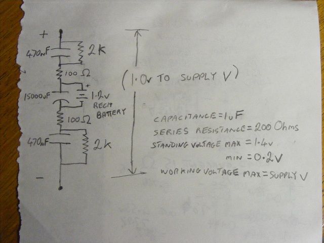
    I'll make a drawing of a possible "modeled Bad battery". Feel free to laugh,
    it's good for the soul.

    Cheers

    P.S. Maybe a "bad battery" model could look something like this. Of course the
    values could all be changed to give a different effect, This setup would have
    a standing voltage of the small battery voltage, the small battery voltage
    would have 4.2 K resistance to discharge, the total voltage could go to the
    supply voltage, series resistance 200 Ohms ect. ect. Surely some kind of
    construction could work as a modeled "bad battery".


    ..
    Last edited by Farmhand; 12-07-2012, 09:57 AM.

    Leave a comment:


  • Farmhand
    replied
    Three Battery System

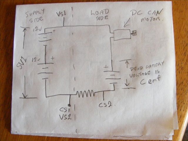
    Hi Carroll, One thing I noticed when first setting up for the experiment is that
    during the time the bad battery and motor are first connected and before the
    motor starts to spin power would be consumed by the dead battery.

    Both the dead battery and the motor are the load.

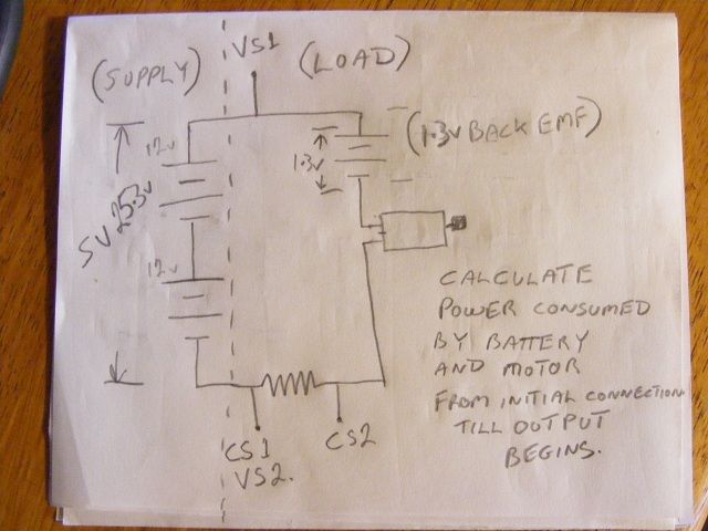
    OK so the first thing I want to collect data on is the amount of power
    dissipated into or by the bad battery and motor from the time of first
    connection until the supposed output starts, then if the net average voltage
    across the resistor shows to be higher on the supply side some charging is
    happening, if the other way the supply is still draining. Or something like that,
    I'll think some more before I start. The voltage of the bad battery would act
    as counter emf so it must be subtracted from the supply voltage to get the
    applied voltage. A reasonable figure in Watt hours should be obtainable for the
    period up until the motor starts to spin, and maybe even after. Some way may
    be needed to detect the time the motor begins to spin. It could take a while.
    While that is happening the bad battery is being charged as far as I can tell,
    and dissipating heat from it's resistance. Consuming power from the supply
    the entire time before the motor starts to spin and produce an output and
    also after, at least during part of the time.

    Either setup should work in a similar way. I used the top drawing configuration


    First thing I will do is try to determine the efficiency.

    It depends on how much power it actually is that is consumed in that time
    before it can be determined where the starting point (break even point) is for
    the efficiency.

    Are the other guys considering the power consumed before the motor starts to
    spin or before the apparent charging of the supply batteries, a reduction in
    the load on a battery will also make it's terminal voltage rise.

    This is my provisional theory below, which I need to prove or disprove.

    My initial impression is that during the time when the motor is not spinning the
    counter emf is only bad the battery voltage basically, then as energy is put
    into the bad battery it's charge increases and it's resistance decreases which
    slightly increases the counter emf it presents to the supply, then when the
    motor begins to spin a counter emf is created in the motor as well, this motor
    counter emf together with the counter emf of the bad battery and the spikes
    generated by the motor may actually allow a reverse emf to be applied to the
    supply batteries. This creates a situation where where the supply was drained
    of charge first then when the motor spins up the counter emf increases
    enough so that the spikes from the motor (emf) add to the BAD battery voltage
    below it like a capacitor and produce a reverse emf to the supply during spike time.
    Then there is the "bounce back" effect to consider as well. When a battery is
    first loaded the terminal voltage drops initially, then as the chemical action of
    the battery catches up the terminal voltage will in fact rise while under
    significant load. Which is demonstrable at any time.

    Lot's of things to consider.

    My first small run showed me that my motor started pretty quickly, it will run
    with very little voltage and power. I see 13.5 volts across the bad battery,
    and the supply battery voltage is dropping very slightly about 2/100 of a volt
    25.3 volts across them so the motor had 11.8 volts across it with 50 mA of
    current which is 0.59 Watts consumed by the motor and 13.5 volts by 50 mA
    for the bad battery power consumed = 0.675 Watts consumed by the bad battery.

    The current sensing resistor has an average current of 50 ma flowing from the
    load into the negative of the supply so it is consuming power.

    If the resistor showed an average net current flowing the other way the
    supply would be charging.

    So far these are the things considered before beginning the actual experiment.

    Maybe I can model a bad battery with some capacitors, resistors and a small
    low voltage battery.


    Cheers

    P.S. Is there a way to determine the batteries internal resistance while it
    holds a charge ? Without a special meter.

    Oh and also I don't have a bad AGM or gell cell, I have a bad flooded lead acid
    battery with very heavy sulfation in one cell which was dry and has been at
    1.3 volts for over 2 years. So there is no reason for the 3BGS guys to take
    any of my results on board, because as I was told an AGM is needed.

    It is not my intention to prove or disprove any person, I just want to
    experiment and see what is happening in my setup. Personally I think the
    effect would be a result of the same causes but without a "properly dead"
    battery the effect may be less or none. Without some way of producing a
    "bad battery" of the kind indicated so they would be very similar from
    experimenter to experimenter a replication is impossible.

    If "replications" are wanted then a standard system needs to be outlined.
    So my experiments will not be accepted as a replication, which is ok with me.

    So to sum up the load power measurements.

    Total load power = 1.265 Watts

    Power consumed by the Bad battery = 0.675 Watts

    Power consumed by the motor = 0.59 Watts

    Total input power is 25.3 volts multiplied by the 0.05 Amp = 1.265 Watts

    Total efficiency is unity. There was no real load except the bad battery and
    there is no real way to tell how much energy was taken on by it as charge
    (charging efficiency) so I'll just consider it all as output so
    0.675 Watts divided by 1.265 Watts = 59 % efficient as far as battery power
    in total is concerned, most of that would be losses due to the resistance
    in the battery.

    Without making any use of the motor or the bad battery the actual efficiency
    would be zero or negative.

    But all that is beside the point. If the supply batteries do charge.

    ..
    Last edited by Farmhand; 12-07-2012, 08:01 AM.

    Leave a comment:


  • citfta
    replied
    Two new serious researchers

    This thread has been quiet for a while but I wanted to welcome a couple of new serious researchers. I have noticed "prompt" and "level" both are interested in real measurements instead of wild speculations. to both of you. Please feel free to ask any questions or make any comments you desire in this thread. Please stick with the technical aspects of the project you are discussing. No name calling or slander please. You will not be asked to leave just because someone does not agree with your opinion.

    Respectfully,
    Carroll

    Leave a comment:


  • Ufopolitics
    replied
    Hello Citfta

    Originally posted by citfta View Post
    Hi Woopy,

    Thank you very much for making that video. Your video shows exactly what I was trying to explain in post #208. It is very clear the current does not reverse even though it appears the voltage does. If the current does not reverse then I do not believe the magnet field reverses either. To test this idea take two bar magnets and with a sheet of plastic or something between them so they don't stick to one another place them side by side so they are attracted to each other. Then try to push one of them beyond the end of the other. When you have moved it only a short ways you will feel it trying to align back up with the other magnet. This is what is happening in the coil the small magnet is trying to stay in the center of the magnetic field so that it's north pole in as close as possible to the south pole of the coil and it's south pole is trying to stay as close as possible to the north pole of the coil. There doesn't have to be any reversal of the magnetic field for the magnet to stay in the middle of the coil. Thanks to you and Farmhand for trying to clear up the confusion of how coils operate.

    Later,
    Carroll
    Hello Citfta,

    I underlined your statements above, it does not happen as you said.
    The Magnet North Up/ Coil North Up, right next to each others, and so on with South to South at bottom...that is how it levitates.
    If You reverse Magnet South Up/Coil North Up...Magnet will not levitate...and if it does, it will make it by reversing in the air, paint or mark poles so you see it.

    Now in the Inductor Voltage does shifts, otherwise Buck and Booster Converters will not work...as they are based on reversal to forward bias through Diode . Current is the Amperage, the Population...that remains the same, Voltage is a Potential difference, reflecting the Higher Populated area versus the lowest other end...Amperage is an electron density...it actually does not have a traveling sense.

    And in order to change the Magnetic Fields you DO need to reverse Voltage, NOT Current, like I wrote above...Current stays the same with Voltage swapping...it is the same population.


    Regards


    Ufopolitics
    Last edited by Ufopolitics; 10-11-2012, 01:27 AM.

    Leave a comment:


  • citfta
    replied
    Hi Woopy,

    Thank you very much for making that video. Your video shows exactly what I was trying to explain in post #208. It is very clear the current does not reverse even though it appears the voltage does. If the current does not reverse then I do not believe the magnet field reverses either. To test this idea take two bar magnets and with a sheet of plastic or something between them so they don't stick to one another place them side by side so they are attracted to each other. Then try to push one of them beyond the end of the other. When you have moved it only a short ways you will feel it trying to align back up with the other magnet. This is what is happening in the coil the small magnet is trying to stay in the center of the magnetic field so that it's north pole in as close as possible to the south pole of the coil and it's south pole is trying to stay as close as possible to the north pole of the coil. There doesn't have to be any reversal of the magnetic field for the magnet to stay in the middle of the coil. Thanks to you and Farmhand for trying to clear up the confusion of how coils operate.

    Later,
    Carroll


    Originally posted by woopy View Post
    Hi UFO HI Farmhand

    I made a small replication of UFO's experiment with levitating magnet.

    I tried to get the voltage pulse versus the current pulse on the scope.
    (notice that for sake of clarity, i have inverted the voltage, channel 1, on the scope screen so the flyback spike do not interfer with the current wave).

    And OK i have to make my homework deeper because, from this experiment, it seems that the magnetic flux Does invert at the end of the pulse. Or the magnet should be propelled out of the coil, or fall out when i reverse the coil with the magnet floating in the middle.

    And ofcourse what is creating this inversion of the magnetric flux, or is there an other explanation.

    Thank's

    good luck at all

    Laurent

    UFO levitating magnet - YouTube

    Leave a comment:


  • Ufopolitics
    replied
    You are Right

    Originally posted by Farmhand View Post
    It works with DC for me and to jump it just takes one single powerful pulse.
    My magnetic field is completely collapsing when I pulse the coil there are some
    oscillations after the discharge but they can be dialed out by duty cycle to show
    a neat square wave with no oscillations, the thing is the coil north is magnetized
    at the same time as the coil south so no matter how short or long the pulses
    are if the magnet levitates into the center it will tend to stay in the center if
    oriented the same way as the coil or tend to be ejected from the center if the
    magnet is oriented the opposite way as the coil. When oriented the same way to
    hover in the coil center the magnet in my experiment was first attracted
    towards the center then held there by repulsion from top and bottom.

    The fact that no pulsing is required and it works with DC tells me the effect
    has nothing whatsoever to do with collapsing magnetic fields in fact the
    effect is stronger with DC not pulsed.

    Mag Lev - YouTube

    Cheers

    Farmhand,

    Yes you are completely right, and I guess I did not test it correctly before...as I just did now, with different sizes and same coil...it also levitates on straight, linear DC...However the Neo, I just touched two times (by error) the connection and it was ejected out of coil...

    Now the "Second Test" will be to put the round or cylindrical magnet into a kind of frame with an axis,all made of copper or non ferrous materials so it could rotate freely...then make same tests...straight DC and Pulsed..

    Note: I did not used a resistor...straight from batteries...it goes up, very strong, and of course did not leave it on, but only seconds.

    Cheers


    Ufopolitics
    Last edited by Ufopolitics; 10-11-2012, 01:08 AM.

    Leave a comment:


  • Farmhand
    replied
    It works with DC for me and to jump it just takes one single powerful pulse.
    My magnetic field is completely collapsing when I pulse the coil there are some
    oscillations after the discharge but they can be dialed out by duty cycle to show
    a neat square wave with no oscillations, the thing is the coil north is magnetized
    at the same time as the coil south so no matter how short or long the pulses
    are if the magnet levitates into the center it will tend to stay in the center if
    oriented the same way as the coil or tend to be ejected from the center if the
    magnet is oriented the opposite way as the coil. When oriented the same way to
    hover in the coil center the magnet in my experiment was first attracted
    towards the center then held there by repulsion from top and bottom.

    The fact that no pulsing is required and it works with DC tells me the effect
    has nothing whatsoever to do with collapsing magnetic fields in fact the
    effect is stronger with DC not pulsed.

    Mag Lev - YouTube

    Cheers

    Leave a comment:


  • codeboundfuture
    replied
    Linear Feed

    Hello Woopy,
    Originally posted by woopy
    is the term linear relative to DC ?
    I believe that Ufopolitics has always referred to uninterrupted DC as "linear feed", ie. a constant voltage from the source (current draw is linear).

    matt
    Last edited by codeboundfuture; 10-10-2012, 09:38 PM.

    Leave a comment:


  • woopy
    replied
    Hi Farmhand

    yes i have tried right now the DC experiment.

    I connected the about same diameter coil with much more winding directly to the 12 volt battery and the magnet levitate and stuck in the middle , same as per my video but very sharply.(did not measure the amperage)

    So your explanation that the magnet has not enough time to fall from the fast pulsating sandwitch magnetic field , which can be seen as per a sliced DC , seems very relevant.

    Or can it be that the magnetic field has no time enough to completely collapse ? Does the magnetic field (flux ) has inertial properties ?

    Just for info i have tried up to 70kHz., and it works also, and very smoothly.

    Perhaps nothing very special in this experiment, but very interesting to feel the difference in the smooth action of this levitation with pulsed current versus DC .

    UFO is the term linear relative to DC ?

    Anyway some thinking experiment ,hope this helps

    Laurent

    Leave a comment:


  • Farmhand
    replied
    Well it works for me with DC through a resistor, with no pulsing. I think I can be
    sure there is no magnetic field reversal with DC.

    My observations tell me it is working how I described in my post above.

    The reason the magnet doesn't keep going is because it is being held in place by repulsion from above and below, as far as I can tell.

    I'll make a video to show some things. And explain what I'm seeing.

    Woopy can you try to levitate the magnet using DC and a high wattage resistor.
    I'm using a large coil though and a few Ohms resistance.

    Cheers

    Leave a comment:


  • woopy
    replied
    Hi UFO HI Farmhand

    I made a small replication of UFO's experiment with levitating magnet.

    I tried to get the voltage pulse versus the current pulse on the scope.
    (notice that for sake of clarity, i have inverted the voltage, channel 1, on the scope screen so the flyback spike do not interfer with the current wave).

    And OK i have to make my homework deeper because, from this experiment, it seems that the magnetic flux Does invert at the end of the pulse. Or the magnet should be propelled out of the coil, or fall out when i reverse the coil with the magnet floating in the middle.

    And ofcourse what is creating this inversion of the magnetric flux, or is there an other explanation.

    Thank's

    good luck at all

    Laurent

    UFO levitating magnet - YouTube

    Leave a comment:

Working...
X