
Opie & Anthony: Stan Meyer's Water Car - YouTubeRotoverter Technology was OU before ORBO one.
All in all if an inventor develops a replicable efficient system the very last place to post full construction details would be in the wolfs den!
Again Its very much a case of personal conjecture but I rather think the world political power and financial systems follow the patterns pretty much laid out in the following quite aged clips and films
The Energy Non-Crisis
Confessions of an Economic Hit Man - YouTube
EndGame HQ full length version - YouTubeProf. Konstantin Meyl the New Tesla on Vimeo
-
Hi Matt, You made an assumption. Just because a setup doesn't harness extraOriginally posted by Matthew Jones View Post
energy doesn't mean it doesn't work for me. I spent quite a bit of time
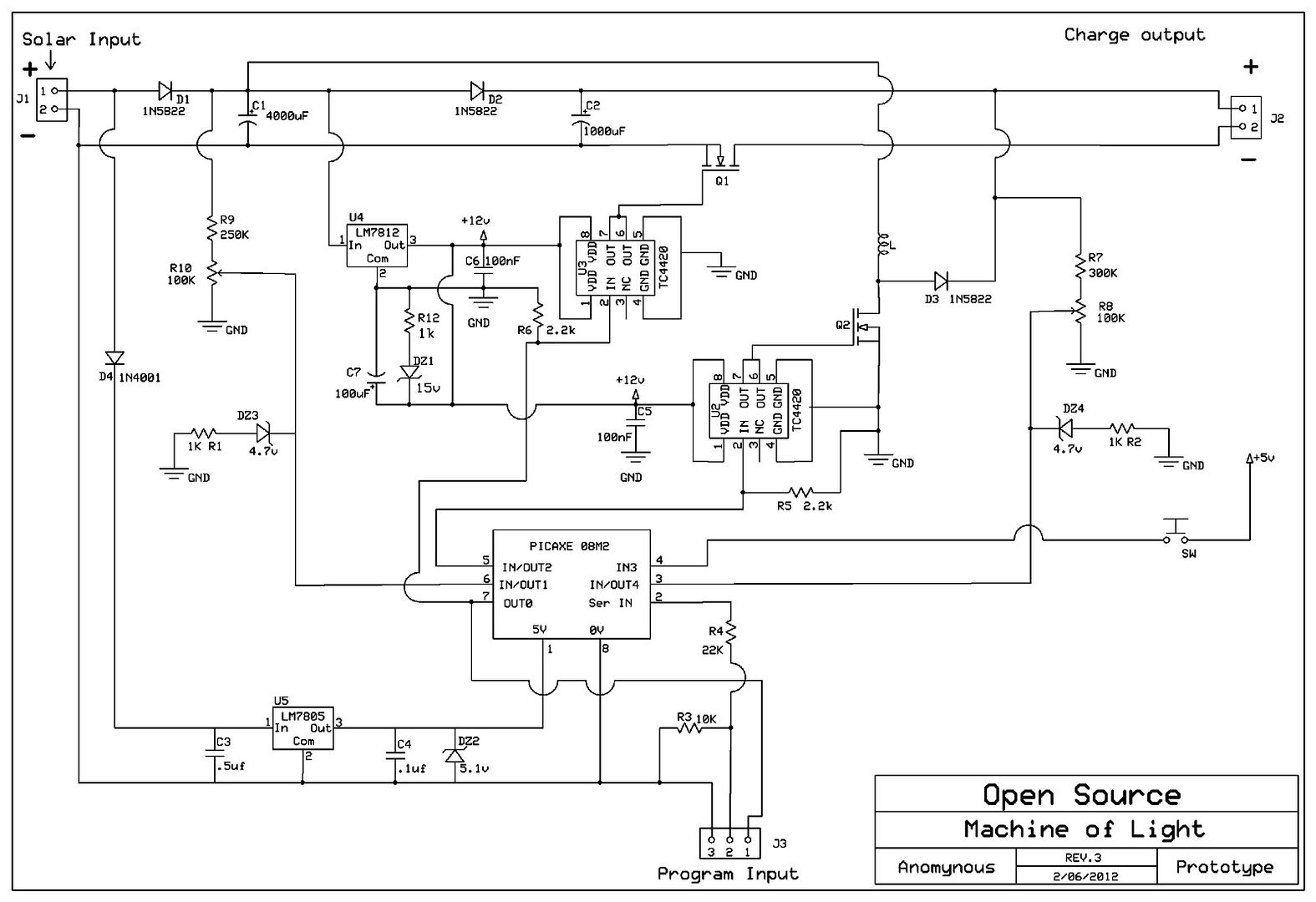
designing a boosting solar charge controller, guess what it works, it pulses the
battery when the light is low by boosting the input voltage into a cap then
dumping.
It charges with the full power of the panels in full sun and it floats the battery
when it's charged. I wanted a system to rejuvenate batteries that looks after
itself so i designed and built it, it's still in testing, been running about
2 months now works great.
Solar controller
Testing solar controller with boost converter for input power - YouTube
Solar Boost Wave forms - YouTube
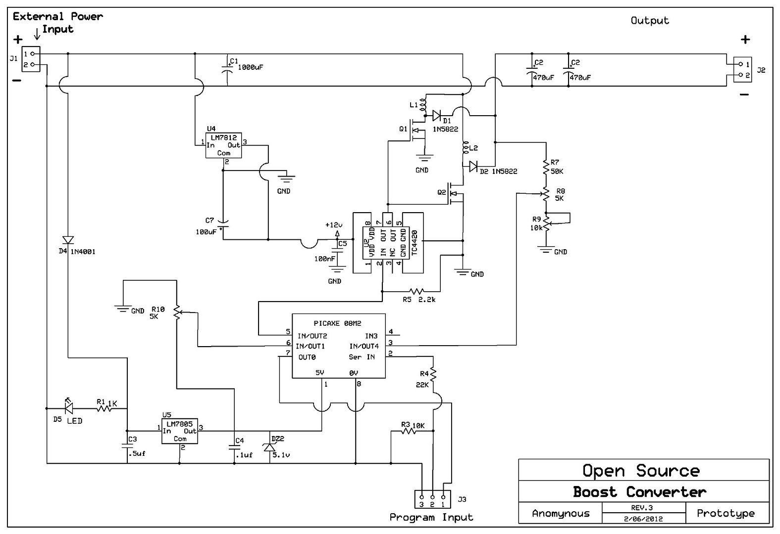
I also built an over 90% efficient boost converter with variable max voltage
and current that can do up to 70 Watts or so. It works very well also. I
wanted a variable power supply so I built it. This one has since been boxed up.
Boost Converter - YouTube
There's not really much use to sharing these because they are custom
devices with custom code, different coils will require different settings. They
are tuned circuits as in they require tuning by a person who understands how
they work. And how to write the code or modify it, I have no teaching. The
code is all mine from what I have come to understand from my own studies,
so it might not be the best way to do it, others might not "get" it. Difficult for
me to say. I see very little interest in micro's and programming on the boards.
Pretty much everything that I expect to work does, things I sometimes don't
expect to work sometimes do. It can take me quite some time to get back to
a project I have put on the back burner. But I'm my own boss I do as I
please. If I really want or need something in my capabilities I get it done.
As far as experimenting goes a result is success the nature of the result is
irrelevant. At the moment I am in the experimenting mode. I expect anything.
Both of these devices use ONLY free energy from the sun, Sol. There is
no gain to be made, it is already done. I have no real desire to try to make
free energy from free energy, I doubt that will happen but I won't deny it if it
does. I have no reason to do that.
CheersLast edited by Farmhand; 10-07-2012, 03:20 AM.Leave a comment:
-
One thing that would convince us that pulse circuits can pull additional ambient energy is to see a self runner, that is still running, and running, and running still.
The Pierse Arrow, Tesla's electric car may have been one of the few proven devices, but, no one can replicate it to this day.
Did he have a little coil in the box in the glove compartment, pulsing away, which could power the electric motor to run that car at 90 miles per hour?
What was in that box?
Billion dollar question...Leave a comment:
-
one might think that energy is spent to build a magnetic field in a conductor/coil.
one might think the equivalent energy is returned while the field is collapsing.
one may wonder whether the spikes people see are merely part of the energy being returned during field collapse in a zero sum game or are they something else?
iether way one might think using the returned energy effectively could aid efficiency.Leave a comment:
-
To Matt
Hi, I've been doing some more experimenting ,trying to make the spikes usable. I made a second bridge that increased the output of the 1st bridge at the same rpm. So I made a 3rd bridge thinking it would also add, but it didn't work.
You said that you have found about 4 ways and to be able to use them on demand, if you have already shared this info ,could you please post links, if you haven't would you be willing to share.
I also hooked 10(20 in total now) more diodes up and the output stays the same.I don't see how this can be
I'll try and draw a schematic to show how it is hooked up.But it won't be pretty
It dosen't make sense that 20 leds' can work ,do leds' not use up the voltage produced by the coil
shyloLeave a comment:
-
Originally posted by Matthew Jones View Post
I've got no complaints with my studies, most of the stuff I do works as I expect it to.
Show the extra energy simple, don't go on at me show something, evidence.
Anyone can say stuff.
I don't know why you would think nothing works out for me. Why would you think that.
I have a negative opinion of people claiming things but providing either no or
insufficient evidence yes.
I wouldn't say I have a negative opinion of peoples work.
CheersLast edited by Farmhand; 10-06-2012, 02:25 AM.Leave a comment:
-
Hi Guys,
I have to agree with Matt on this one. I HAVE seen things that conventional logic says can't be. The clearest one was the time I got the Tesla Switch to run for a solid week powering its own switching circuit and a few Leds and the batteries voltages did not drop at all during that time. I was checking them every few hours and the voltage never dropped even as much as .01 volts on any of the batteries. These were the small 12 volt 7 AH batteries.
I have also a few times gotten the 3BGS to run much larger loads than it should be able to and the batteries fell very slowly or seemed to not drop at all. I know battery voltage is not a good indicator of what is really going on but after several times of doing that it sure seems like something is going on that is not explained by conventional understanding of electronics. I certainly plan to keep on working with the 3BGS until I understand it or come to the conclusion I will not be able to understand it enough to be able to use it as a reliable source of power.
I am in the process of building a new workshop area where I will be able to do more than one thing at a time and hope to try some new ideas I have seen posted lately. Hopefully I can start moving into it in a couple of weeks. I almost have all the wiring done with lots of outlets for plenty of test equipment and power supplies. I need to get some test benches and shelves built next. I wouldn't be going to all this trouble and expense if I didn't believe in the search for answers as to why some circuits seem to produce more power than they should be able to.
Later,
CarrollLeave a comment:
-
That explains why you generally have negative opinion of peoples work. I would have never continued on looking had I not seen it in the monopole..Originally posted by Farmhand View Post
Have you never built a monopole to spec? Or never seen a COP in your batteries charge higher than 1?
I have found about 4 ways now that prove extra energy from transient spikes. I have found how to bring them into forward time on demand to make them usable extra power.
Carroll, I am sure, will back it up. He's seen it in his own work first hand.
I am not trying beat up on ya, I just am real curious as to why you would even bother looking any further if nothing seems to work out for ya..
MattLeave a comment:
-
Hi shylo, I guess you're right I didn't really word that the best. The thing is,
most people don't do that, usually a load is between the terminals or ends of the
output coil. The question is. If you call that a "short circuit" then what is the
"normal circuit" in that setup. As you point out there is no output while the
output of the coil is shorted.
I don't consider shorting a cap to discharge it for safety to be a "short circuit"
as such. Lots of things cause voltage spikes. I don't want to go into my
opinions on shorting coils. It can be useful.
The point is an "open" switch is open, when a switch is opened it is turned off.
To turn the switch on, it is closed. This is my understanding of the accepted
meaning. Who is right and who is wrong is irrelevant, the main thing is that to
collaborate people should agree on terms. There is no need to change what is
generally accepted if it makes no real difference.
It's generally accepted that a "short circuit" is an unwanted and unintended event. But I do agree it can be done on purpose.
Keep plugging away, we all do.
CheersLeave a comment:
-
To Farmhand
Hi ,Perhaps I us the term" shorting the coil " incorrectly?
That homade reed switch I'm using shorts the coil leads together with the passing of the magnets on my rotor (nsns...)
"A short circut is an unwanted shortening of the current path in a circut"
The led bridge (without the reed) stops blinking when the rpm slows down ,but with the reed connected the bridge blinks at almost a stand stil super slow rpm.
I think when the leads are shorted together nothing happens but the instant they open there is a spike ,the spike settels down, but that instantenous spike, is what can add to make for better output.
I'll keep plugggin away at it.
shyloLeave a comment:
-
I agree with points from both sides again.
In my opinion Pulse Width Modulation capable circuit need not be always
modulating the pulse width but it does imply that the modulation is automatic.
However if one were to adjust the pulse width it could be considered a
modulation. Regardless the general conception I think is that the Pulse width is
variable on the fly not fixed.
As for the open switch thing it's simple.
An open switch does not conduct. When a switch is closed it is on. When a
switch is open it is "off".
Which is in line with an open circuit being "non conducting".
And with a closed circuit being "conducting".
A "short circuit" is an unwanted shortening of a current path in a circuit.
I think it is very important if we want to understand each other and
collaborate that we at least know, and or explain what we mean if there is a
possibility of mixed terms.
I did start a thread on terms and definitions but it got sidetracked. I thought
it was a good idea but no use if no one can agree, a thread like that should
be made and then made a sticky so it's there to refer to.
For now I see no use in trying to collaborate with people who see things so
differently. There is nothing special about the reuse of the energy from the
collapsing magnetic field, it's common practice in well designed circuits and
devices. It is also commonly used in boost converters and such things to
increase voltage.
Power supplies and some motors use PWM for power control, what is not
generally done is recovery of the energy from the collapsing field of pulsed
motors, when it is implemented it can increase efficiency to be closer to 100%.
I have not seen any definitive evidence of more energy out of a circuit than is
put into a circuit from a supply, not in any motor or transformer switched or
otherwise without another source of energy such as wind, solar ect..
I have not seen any convincing evidence that "extra" energy can be pulled
into a circuit by the collapsing magnetic field.
CheersLeave a comment:
-
Open Transistor (referring to MOSFET's)
Originally posted by citfta View Post
Hello Dear Carroll,
I use that term or "Open"...very often...and I find it perfectly correct.
First, I use it mainly when referring to MOSFET's in a Controller or Oscillator Circuit...as I have also utilized it on my videos...
A MOSFET (Metal Oxide Semiconductor Field Effect Transistor), is basically a SWITCH, except it is an Electronic Switch...and as far as I know in the simple and common knowledge about plain circuit electricity of first year...a switch is either Open...or Closed...nothing else...unless it is a "Special Design Switch" with a resistance dimmer...normally used in lighting systems...and other applications....where it could be set at different resistance values.
MOSFET's are EXACTLY, like the old Relay (Magnetic switch)...the difference is that a relay uses the magnetic field to attract the conducting plate...while the FET's uses the atomic electronic structure of its materials at the gates-source-drain configurations. However both "SWITCHES" use a low voltage commanding signal to execute the switching at Higher Voltages through their different means...one electromagnetic, the other electronically...
Remember one of the spec's FET's are selected by is their "SWITCHING CAPABILITIES"...like Ultra-fast Switchers or Slow Switchers...
As I also understand there are other Transistors dedicated to other Functions that are not "Switchers"...like a Voltage Regulator Transistor...or an Audio-Pair Amplifier Transistor...as many, many others out there...Now to this other types of semiconductors, I really understand that saying..."Transistor is open"...means it is not good...like you have written above.
Regards
UfopoliticsLeave a comment:
-
Pwm
Hello dR Green,Originally posted by dR-Green View Post
The question was addressed to me...by Member Selnet. I have been guiding him on a 10 pole asymmetric machine replication...
As I am able to understand what you are referring to...I am also capable to understand what Selnet is referring to...
And You are right, a PWM is a variation over time of A signal, where Duty Cycle and also Frequency could be adjusted by just one Potentiometer attached to the Oscillator Chip triggering tank circuit.
It is very easy to see this signal vary on a Scope...
Where I disagree with you...is the way you "separate" so drastically Square Wave from PWM...A Square wave "NOT necessarily" needs to be ONLY manifested in a "Fix" shape...it could also be Modulated
Let's put it this way...
PWM is an action, a verb, an execution to ANY given Signal, which is to Modulate it...it could be Square, Triangular or Sine wave...
Square Wave is a Noun to a Signal of certain characteristics, "A Type of Signal"...which in nature forms square angles, and not sharp, critical angles like Saw Tooth or Triangle Wave... or Soft Curves like we see in a Sine Wave...
And of course they ALL could be arranged in any given circuit to be of "Fixed Parameters" example: amplitude, peaks and equal displacement through time...
Time dimension goes through ALL of them...we can not alter time...or "prevent" from being "there"...They could remain EXACTLY SAME Parameters through time...
As time could be also "Infinite".
Now, in Motor Controllers Terms, a PWM is a method utilized to excite, run Motors, at different speeds, this Method have taken over the old fashion Linear Potentiometer-Resistance based controllers.
Now, Selnet was referring to that particular PWM Controller, and yes, there are circuits where We can Modulate Duty Cycle separated from Frequency (Dual Potentiometers) over time...BUT, We could always -once reached- leave it right there...
The question arose due that Selnet is looking for the suitable parameters where Motor-Generator will produce Max Outputs Values.
I have an example: Member Netica has a video where He is showing a Typical Symmetric Motor fed by the "C EMF" or the Spikes, or the Radiant Energy generated when Pulsing Modulating the Square Wave of His Coil...Motor runs cold...no sparks...and when applying a mechanical load, Amperage does not increase "on the other side"...the Hot side, but the reason I am bringing this example...is because this "phenomena" only manifests at specific Duty Cycles Percentages as also specific Frequencies...and, just altering one of them...it will not happen...interesting right?
So, do you think..."This Guru"...or "Teacher" has the knowledge to answer that question...or not?... Sir?...
Regards
UfopoliticsLast edited by Ufopolitics; 10-05-2012, 04:32 AM.Leave a comment:
Leave a comment: