
Hi Voltan,
Your desire to have one winding in the tank is possible but to extract energy you have to find some impedance matching means to a load or to another circuit, and such matching can easierly be done by tinkering of the number of turns of a coupling coil to sniff the energy out from the tank. Even so you may lose half of the power when a power match is achieved, unfortunately. (power match happens when your load impedance equals to that of the output impedance of the oscillator, you surely know this)
I can see you found a push-pull oscillator which works like an astable RC oscillator of course except that the R components in the collectors are replaced by a coil or coils.
You can find many schematics by the way by using google Pictures with key words like 'push pull oscillator circuits'. Already wanted to show this link,
Oscillators - part 4
scroll down to circuit 21.Push-pull LC oscillator. (there are some other interesting circuits there)
For pic 2 circuit the power level can be increased by biasing the transistors to higher current with the base bias resistors but the limit is frequency stability.
If you have access to a junk AM pocket radio of the 70s, they used audio output transformers in their push-pull audio amplifier, you could use such here for the center tapped coil. But then it would not be a single coil tank...
It is always good to vary the DC supply voltage for such oscillators, it is easier to find the best oscillation conditions, output etc. IF you have not got a variable DC supply, you could connect some AA batteries in series to have a few voltage values available in 1.2 or 1.5V steps.
Gyula
-
thanks again gyula. i have deleted a few posts including the dud schematic. i haven't found another osc. circuit on the net, that uses an iso trafo for feedback. so far pic 1 is about as close as it gets. not a bad looking scheme. i would like a scheme with 1 winding in the tank inductor, that delivers the same result, if it's possible.
* i just found pic 2 on the talking electronics site. it looks like a flea power circuit. maybe it can be beefed up.
cheers.Attached FilesLast edited by voltan; 07-20-2015, 05:14 AM.Leave a comment:
-
-
Hi Voltan,
Okay on the piezo starter for the oscillators, neat idea.
Regarding the differing frequencies at the base and the collector, I suppose what you measure at the tank LC circuit (collectors) is what the actual oscillating freq is and a freq meter may be fooled at the base where there may be no clean and close to sinusoid waveforms and these can trigger the counter gate inside the meter twice.
But this could be checked by an oscilloscope or by using a very light coupling between the input of the freq counter and the circuit measuring point. Depending on the input sensitivity and impedance of the meter, try to use a series coupling capacitor of say 100pF as a start to check the frequencies again and if you get again the double freq at the base then try to use even less value coupling cap.
A choke coil is normally inserted in the wire of the supply voltage that leads to the center tap of the tank coil.
In your second schematic the collectors still cannot receive DC supply voltage via the capacitive dividers, you surely know that.
GyulaLeave a comment:
-
Hi Voltan,
In your 2nd schematic the collectors of the transistors cannot receive battery voltage through the capacitive divider. In the first schematic the center tap (or the common point) of the two coils can insure it.
One more issue: in none of the schematics are the DC bias voltages provided, this involves the start up of the oscillators will be casual or impossible.
GyulaLast edited by gyula; 07-15-2015, 10:47 PM.Leave a comment:
-
Hi voltan,
Your posts about using neon bulbs as oscillators brings back old memories. Back in the 1950's you could buy a "B" battery. It was a rectangular battery that put out 70 volts. It was used to power portable tube type radios before transistor radios became common. My dad had a TV repair shop and liked to tinker with electronics also. He built a small circuit right on top of a B battery with 3 neon bulbs and some caps and resistors. It was basically a relaxation oscillator times 3. The neon bulbs would fire randomly and so it would sit there and just blink on and off. It used such a small amount of current that it ran continually for several months before the battery ran down. He used neons that fired at 55 volts if I remember correctly.
Thanks for contributing to the thread.
CarrollLeave a comment:
-
hi all. i was surprised to find an old circuit that uses a pigtail neon to generate a sawtooth wave. i will try putting the search coil in series with the neon. maybe a cap across the coil, a tank circuit in series with the neon. ionisation/de limits frequency to about 20 khz. it would need a supply capable of up to 100v. R is a very high value, so a joule thief on the front end might power it ok.
could be interesting to play with.
*** i got this to run. with R 1 meg, C 681/680p it makes a tone at about 11 khz in my headphones, with the search coil in series with the neon. the j.t can maintain the oscillation with as little as 2 ma at about 7v input. it's a small signal and it's a bit unstable, but not bad for it's simplicity.
early testing as a metal detector showed a much increased sensitivity to local capacitance. eg. moving a hand near any part of the circuit, but sensitivity to eddy currents in a metal sample changing the search coil's inductance is what i'm after. wihout the coil the neon is R C timed. with the search coil it has a weak response to metal objects,(running on flea power at this stage tho.), so L has some effect on the resonant frequency. i think making R variable is worth a try.maybe i can improve the sensitivity to inductance changes if i try swapping some components around.
later testing with a variable 1 meg resistor and a 2.5 uf film cap across the coil showed comparable sensitivity to metal objects to the other circuits i have tried.lotsa harmonics on the a.m band tho.
i guess a xenon flash tube could function like this with lotsa volts and the right R C values. could make a nice display piece if it doesn't run hot.maybe apply uv output shielding.
imo this is a great article.
cheers.Attached FilesLast edited by voltan; 07-08-2015, 09:37 PM.Leave a comment:
-
-
hi all. while your on the subject of motors check out these 2 short vids of what i believe aaron, john and peter have been working on quietly together. these are 2 zero force motors if your not familiar.
i haven't built anything like this, but clearly they are mounting stator magnetic fields at right angles to normal and reducing, if not minimizing lenz effects in these prototypes .
recently i discovered you can use led timing lights to indicate or sense peak or near peak voltage in a parallel tank circuit. i got a joule thief circuit running with a cap across the primary coil. pic 1. both it and the sec winding form the air cored search coil. but i doubt that a blocking oscillator just happens to provide efficient running of a simple tank circuit.so i think i can achieve stronger resonance for less milliamps input with a better strategy for maintaining oscillations.
another goal with an analogue metal detector is to make it oscillate the search coil with a nice clean sine wave in an effort to reduce losses to multiple harmonic frequencies. presumably the more eddy currents in a metal target circulating at the fundamental freq., the better the response for stronger detection.
there are several ways to look at this. 1 think of pushing a kid on a swing. you push just after the change of direction to build up momentum,inertia,travel and height. 2 a solar pendulum flower pot toy senses bottom dead centre and fires a pulse to accelerate the magnet at the bottom of the pendulum with repulsion in alternating directions.
3 then there is parametric excitation,which is like getting yourself up to speed and height on a swing when there is no-one to push you.you can lean backwards and forwards, shift the centre of gravity at 1 or both points of max travel and build up your oscillations.
i'm thinking topping up the cap voltage, right on both peaks,with a short or limited pulse, of the appropriate polarity through every cycle, is 1 way to maintain strong resonance with low consumption, due to maxed impedance.
so does anyone know of a circuit that could trigger these top-up pulses at the best timing, possibly using my led peak detectors for timing sensors. i think something like a one shot multivibrator or 2 is what i need.maybe an adaptation of the pulsing circuit in my first post here. without a scope i'm guessing in a lot of ways, but i can tell when harmonic frequencies are quiet on an am radio held close. most of my experimenting is in the 13-20 khz range. pic 2 is a neat colpitts osc. that makes a nice sine wave at 500 k-1 mhz depending on the search coil size and turns, but it only draws 1.2 ma on a 961khz coil i made.it's a strange looking circuit, but very efficient. hard to soup up tho. as a metal detector it has good sensitivity in free air, but by all accounts mid to high audio frequencies give the best ground penetration. so i tune the tank circuit to get down into that range with these circuits.
i know there are other proper sine wave oscillators like pic 2 on the net. i just want to explore some alternative concepts.
cheers.Attached FilesLast edited by voltan; 07-13-2015, 01:15 AM.Leave a comment:
-
-
Universal solution for problems concerning many claimed "free energy" devices:

Leave a comment:
-
Originally posted by kenssurplus View Post
You do not have to short directly, you can also just reverse the coil and allow the coils to short to source, No Plasma, charge stays in the system.
MattLast edited by Matthew Jones; 07-02-2015, 10:08 AM.Leave a comment:
-
This is my coil shorting commutator after being run though shorting tests. You can see the plasma marks from the brushes on the teflon plastic insulator sections.
Really about the only way I can think of to use a conventional dc brushed motor and adapt more brushes and affect control positioning of those brushes is to convert it into an outrunner by drilling out the shaft, running all coil leads through the shaft hole to the outside. Mount the shaft stationary and spin the outside case. Lotta work though.
I have some more outrunner motors if you are interested in playing with that topology.Leave a comment:
-
short switches and send power to the dump
Thanks Carroll for the reply and interest in my efforts. One of the other reasons the cap switching commutator was never finnished was, I realised that I needed individual pressure control on each brush, and the way I built the brush towers, they were all glued together so one adjustment for each tower.
If I had thought about it some more, and given it more tries, I could have come up with a workable solution. But life has a way of taking your steering wheel away from you and handing you back your plans in a dust bin.
Artv, My system was so much easier to work on, being it was an outrunner, so I could have acess to all the windings, and brushes / commutator sections outside of the generating and housing area. I also drove the gen with a Rotoverter motor, which meant I wasn't dealing with motoring the windings and then switching them out for generation / shorting. That may be a way to configure your switching needs, as I had total phase control (where in the waveform I wanted to short), duty cycle per short (how wide of a time slice the short lasted) and each phase separately controlled from each other - all on the fly while the unit was running. I can see that for motoring and then generating and then shorting then switching for serial / parallel cap dumping, that would get complex in a hurry. - especially if it was a typical dc brushed motor.
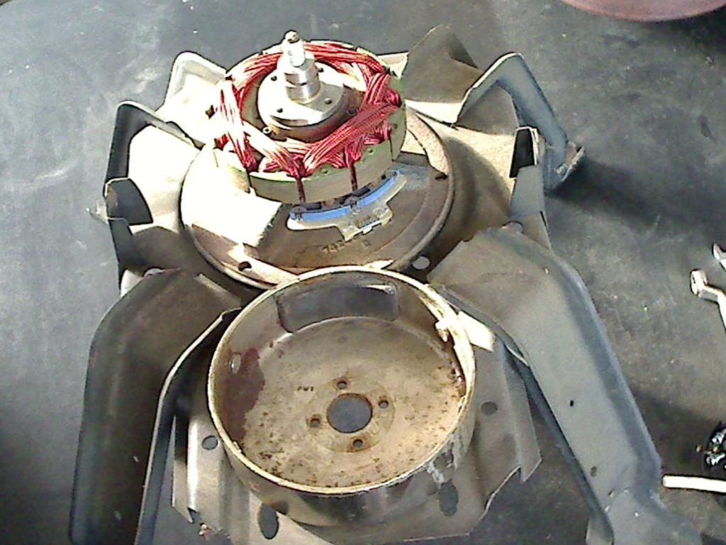
This is one of the outrunner motors. This one had some magnet damage, and only has one original magnet left.
Here it is with the outrunner bell on:
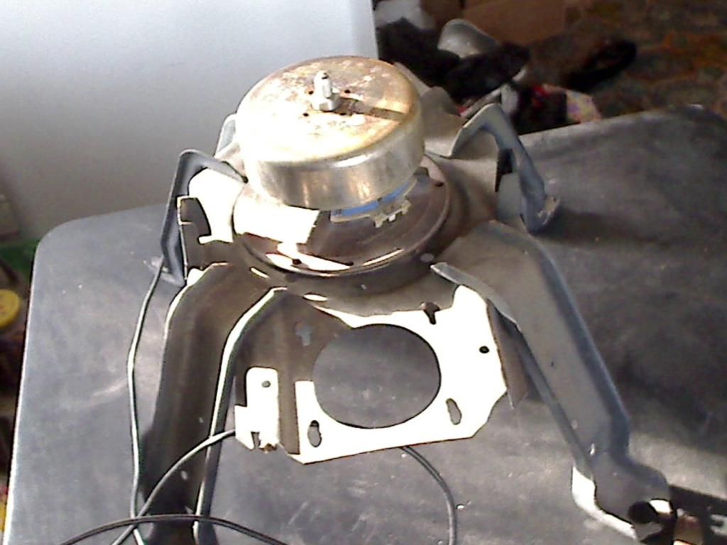 Last edited by kenssurplus; 06-30-2015, 11:06 PM.
Leave a comment:
-
Hi Ken, I am shorting ,or trying to short , when the power coil is just turning off.
Collect the spike from power off, store it and , re-inject it to the supply.
Plus add in the generated power from the collector brushes.
I have to get my switch to work. As the charge builds from generation , if you short it , a big spike occurs, use the generation before the short and the spike is bigger.
Still trying to make my caps dump at the right time.
artvLeave a comment:
-
Well??????Originally posted by Ernst View Post
This guy is claiming to refer to Tesla for making his youtube video.
So let us also refer to Tesla.
Where is it???
It's not there, is it. He's lying to you. He's telling you absolute rubbish. But you don't care. Instead you will defend him and argue with me for pointing it out.
Useless.Leave a comment:
-
Nope. You are talking about Tesla's invention/discovery. So I give you Tesla's account/description. One would assume that under normal circumstances such a thing would be helpful, you see.Originally posted by DavidE View Post
There is no need for ignorant people on youtube to devise nonsense theories and explanations, an explanation already exists. If they had any sense then I would have nothing to say. But, they are not even aware that Tesla's explanation exists such is their ignorance. And then they proceed to explain it "in their own words". Frankly I have zero faith and trust in their abilities and credibility. They have not done one thing to show that they know what they're doing or talking about, it's just nonsense. There is no difference between that and a science fiction writer, they are empty words and none of it even NEEDS to be based on reality. But you and others who are deliberately "searching for magic" are REJECTING the sensible explanation and preferring some nonsense that doesn't and can't make sense. That's the bit I'm responding to.
Also, as I have pointed out, a "Tesla coil" is all you need to start with single wire experiments, there's no need for anything else. You can complicate it as much as you like with useless information, but there's no need for any more than the basic setup. All the youtube trash WILL NOT teach you anything useful whatsoever if you have not learned the BASICS, they only will lead you further info confusion. Apparently you wanted to argue with me for saying such a thing, so here we are. I might also point out that it would waste a lot less of my time if I simply allowed the disinformants to run amok.Leave a comment:


Leave a comment: