If this is your first visit, be sure to
check out the FAQ by clicking the
link above. You may have to register
before you can post: click the register link above to proceed. To start viewing messages,
select the forum that you want to visit from the selection below.
I was just sent this in a private message. Reggie has been interviewed on CNN claiming he is going to save the world with his new invention. Plus, he is going to sell some old photos of Michael Jackson to fund his project.
I have built an electric motor EXACTLY the way Peter told us to, and have posted pictures of it previously, which is ALWAYS my first step, and I continue to experiment with THAT motor and its applications. Don't build what I am about to show you until you have followed Peter's directions for a rebuilt motor TO THE LETTER.
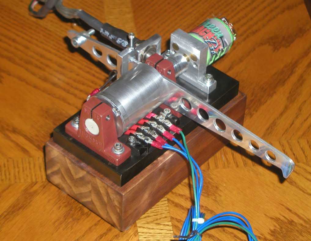
I did, however, want to share that I took apart a car alternator. I removed the rotor and replaced it with one I made out of a 3/4 inch steel bolt I had machined to the same measurements as the previous shaft, except longer so it sticks out one end of the alternator. There are 42 slots on the commutator for coils, so let your imagination work on different possible combinations there. I chose three magnets on the rotor and three groups of 3 on, 11 off on the stator. I could have gone with 4 groups of 5 on and 8 off with 4 magnets on the rotor, and I may go buy another alternator or two at the junk yard, pull the stators out, and experiment with different coil configurations to see what happens. I could also replace the rotor with one that has four magnets on it. I am having a rotor hub made that will slide onto my center shaft that I can bolt different configurations of magnets to (made out of steel with a set screw to tighten it on the shaft) but for now I am using a plastic rotor with magnets attached. The main reason I did this is because it eliminates the need for brushes, and I just HATE those brushes!! I have two videos posted at You Tube, and will soon be using this motor to pulse my generator. Will let all know how it turns out.
I can appreciate your interest in the "Muller Motor Demonstration" video, but there are threads dedicated to that elsewhere on this forum. Please post your comments on that topic in the appropriate threads. This thread is for people interested in experimenting with modified DC motors to produce a torque enhancement by lowering the back EMF/forward EMF ratio.
The only problem with flywheel that has the weight on the outside is it takes more work to get it up to speed.
The real trick would be to have the weight start on inside then move out slowly as the speed was gained. Then start pulling a load off of it from the inside.
Matt
Yes, interesting point. Thanks.
Although I'm mechanically challenged, the first thought that comes to mind is to chop the flywheel mass up into a number of heavy, short, cylinders tapped in the middle.
Mount the cylinders on threaded "spokes" radiating away from the hub.
Screw the cylinders down all the way to the hub.
Start the machine.
The centrifugal force causes the cylinders to twist (screw) themselves outward to the maximum outward extension. The screwing action slows the the outward movement of the cylinders, giving the motor a bit of startup leeway.
The generator magnets cannot be mounted on the spokes since they would interfere with the outward motion of the weights, so add a second (low mass) disk to the motor shaft holding the magnets.
[Ideally, but impractially (?), the magnets would also be mounted on threaded spokes and would wind themselves out from the hub to the middle position (and end up in the correct NS orientation), without banging into the generator pickup coils in the process.]
pt
add: This cylinder/screw arrangement is the mechanical equivalent of an electronic coil (inductor). It resists rapid change in momentum. The threaded cylinder has to wind its way out to the perimeter by "looping" (spiraling, screwing) around, instead of just whipping out to the perimeter if it was simply mounted on a smooth spoke with no threads.
Last edited by pault; 05-10-2011, 04:52 AM.
Reason: footnote
The only problem with flywheel that has the weight on the outside is it takes more work to get it up to speed.
The real trick would be to have the weight start on inside then move out slowly as the speed was gained. Then start pulling a load off of it from the inside.
Interesting idea (on Muller thread) about the use of leverage.
Position the drive coils at the outside of the disk and the generator coils closer to center of the disk to gain (some) advantage of leveraging drive coil force over generator coil drag.
From that perspective, my mod'ed DC motor is inside-out. The drive shaft is in the center, and my experimental generator disk has its magnets about 6" radially out from the center.
I might be able to take advantage of this idea, if I were to build a suitable flywheel with most of its mass at the outside, then position the generator magnets closer to the center. Hmmm. OTOH, maybe it doesn't matter (much) where the magnets are, once the flywheel is up to speed. More thought required.
I've read about 1/2 of the posts (thread growing rapidly today).
Here's what I've gleaned, in the hopes it saves you time / head-scratching. Don't assume that my understanding is correct, comments welcome.
His rotor contains 8 magnets, all pointing in the same direction, sandwiched between two stators.
Each stator has 9 coils, 300 turns, about 36AWG (litzed). Each top stator coil is in series with its bottom partner, i.e. each of the coils is really 600 turns, and the rotor cuts through the middle (cross-section) of the coils.
Of the 9 (compound) coils, two are used as drive coils - that's our rewound motor. So, we could drop 2 of the coils (and 2 of the magnets???).
The other 7 coils are generator coils, each dumped into a separate FWBR. All FWBR outputs are connected in parallel to a cap.
The cap is connected to a DC-DC converter (12VDC to DC1.5, 3, 4.5, 5, 6, 9 and 12V). He claims he needed the converter to stop "burning out" his coils. I'm guessing a direct connection from the cap to the 2 drive coils produced flybacks high enough to hurt his wires, and that the converter smooths that out. That's what our recovery brushes are for, but it bears some thought as to whether a "regulator" might be of assisstance to our stuff.
The output of the DC-DC converter is put back into the two drive coils. Each drive coil is pulsed with a Hall-effect circuit (we are using the motor's commutator to pulse it).
And, in parallel, a 12VDC, 20W light bulb is connected to the output of the DC-DC converter.
The fact that there are an odd number of coils and an even number of magnets appears to be significant.
He says to tune the machine with the light-bulb in place. He appears to tune it for a smooth ride by adding extra magnets on top of some of the coils (side opposite the rotor).
He's attached a 2nd set of diodes across each of the FWBR's. I'm not yet sure if that's to increase current or to decrease diode forward voltage.
His "flywheel" is the thick plastic rotor disk.
He says that using Litz'ed wire is more productive than plain.
There are, certainly, some parallels to the Lockridge-like motor we're working on.
He's probably got less drag (better spin time) than our off-the-shelf motors.
More thoughts (if any :-) later.
pt
Last edited by pault; 05-08-2011, 06:50 PM.
Reason: added thought
It WORKSSSSSSSSSSSSSSSSSSSSSSSSSSSSSSSSSSSSSSSSSSSSSS SSS !
I am going to upload the video, is almost 20 minutes of self running.
The skeptics should prepare the arsenal.....
I've been spending a lot of time researching this motor issue. The brushes are a pain in the butt. I was thinking that what we really need would be a motor with the permanent magnets on the rotor, and the coils on the stator, around the outside. I know this isn't exactly what Peter described to us, but I am wondering if this would significantly affect performance, or even kill it. For the life of me, I don't know WHY it would, but then I'm not the expert, and Peter certainly is. I suppose the magnetic field might have a tremendous amount to do with it.
Anyway, I have approached this from two different directions. First, I ordered a brushless 12 volt DC motor from this web site N2311S018
It is set up the way I described, with neo magnets on the rotor and windings around the outside on the stator. Just exactly what those windings look like, I don't know. Still looking for specs on that particular motor that will tell me. The link to specs on the motor page doesn't show how the windings go. I want one for some other things I am doing, so if it doesn't pan out for this project, so be it.
The second thing I did was take apart a standard car alternator I got from a junkyard and replace the entire rotor with a 3/4', 12" long steel bolt that I had machined down to fit into the bearings at one end, and through the bearing and case at the other end so I would have a shaft to work with. Because there are 42 slots in the stator for windings, I have gone with 3, wound, 11 off 3 wound, 11 off 3 wound, 11 off. The rotor will be triangular with magnets in three locations and it will fire three times per revolution. I drilled a 3/4 hole in some plastic, stuck it on my bench grinder to spin it, so that I could make it perfectly round, and then cut slots in it for magnets. Now I have a rotor with magnets on it for my testing. I'm not finished with it yet, so I will let you all know if it actually works. If not, I only have myself to blame.
I DID build a motor exactly the way Peter told us to, and I'm very happy with the way it is performing. I always try to follow directions EXACTLY before I go off and do something different. Just hate those brushes, and wanted to figure out a way to eliminate them. Maybe I'll find that the brushes are critical to performance. Stranger things have been known to happen!


Leave a comment: