Hi Penno64
With the 2 pole motor your using there is no way to wind a zig-zag style, that is for a 4 pole motor.
With the 2 pole motor you also dont need a diode. With a diode your motor will only fire 1 time per revolution. Without the diode it will fire twice per revolution.
You may also want to hook 2 commutator sections together where your coil wires are hooked up so you can have a longer "on" time. This will get that motor really going.
I also did not see any recovery brushes in your pictures. Without the recovery brushes you will have lots of arcing and will burn up your power brushes quickly.
I'm not sure how many volts you used to run your motor but you also need to increase the voltage, remember that the way your motor is now with only 1 pulse per revolution and only using 1 commutator section you have an effective on time of only 8-9%.
-
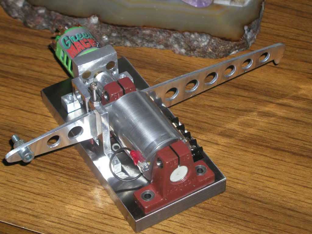
Here's a few pics.
The magnet rotor was simply used as flywheel.
ThanksLeave a comment:
-
Hi Matt,
Thanks for the reply.
Yes it a 2 pole (2 magnet) motor.
I have soldered the diode in the other way, but still no run.
I added some weight and found that it will run - just!.
And yes, I had it wound as you detailed.
Matt, from Peter's comment regarding your Z-type wind, I feel we need a different way of winding for the 2 magnet motor.
Using Brian's offset brush placement, means I can eliminate the internal diode, so
I will need to do some work on the brush holder.
Once again, Thanks for the advice.
I will post a couple of Pics if time permits.
Kindest Regards, PennoLeave a comment:
-
Thats some pretty work. Looking forward to seeing your results.Originally posted by joeqsmith View Post
What happened with the diode? How many magnets in the motor?Originally posted by penno64 View Post
If you have 2 magnets.....
Your winding should start on the same side as the commutator go through slot 1 and down to 6, and back up to one.
looking at the rotor from the commutator you should use 2 slot of the commutator to left of the wire slot.
Your motor will be a puller if wound this way.
If you need a drawing ask. But give all the specifics of the motor you have, or link to the one your talking about.
Cheers
MattLeave a comment:
-
Some help please.
After several attempts at different windings, I must declare that I am beaten.
My setup is similar to that which Turion showed a few pages back and that
which Brian (n84dafun) shows.
Razor scooter B1308222 motor
2 pole
12 segments
12 slots
I now understand why I get 1 pulse at 0 degress and a reverse pulse at 180.
Hence, no continued motion.
I tried the diode, but no joy.
I clearly see the z-type winding for Matt's 4 pole setup, though I cannot see
how to apply this to the two pole with 12 slots.
I will keep going while the skin on my fingers holds up, but would greatly appreciate any advice.
Kindest Regards, PennoLast edited by penno64; 04-22-2011, 08:33 AM.Leave a comment:
-
The first dyno was damaged and had enough design problems that it was not worth repairing. This is my second attempt at an improved dyno.
Base is steel
Absorber is brushless
Absorber bearings are full ceramic
All other bearings are hybrids
No shims
Only one drive shaft to connect test motor to coupler
Total drag with synthetic lube in all five bearings is much less than first dyno
Electronics are the same except the bridge added for the new absorber
I estimate this dyno will easily handle shaft speeds in the 30-40,000 RPM range and should allow measurements to 150 Watts.
Leave a comment:
-
Deleted off topic drivel...Last edited by WeThePeople; 04-22-2011, 09:24 AM.Leave a comment:
-
I think somehow he thought he could pull it off.
You can only thank stupid people, they set the bottom of the bar for everybody else.
MattLeave a comment:
-
Looked like a post-&-run, doubt he'll be back...
Give him a piece of your mind directly instead:
GoReggie = Reginald Garcia
YouTube - goreggie100's Channel
"Electric Motor Company (of) America":
http://www.EMCoAmerica.com/Contacts.html
951-300-3371 = Sprint/NexTel cell phone
Telephone Number IDentification - Searching
GoReggie2@Verizon.net
He is also listed as a "Manager" for fire alarm services here:
"TDC Communications":
Contact Us
CCTV Security TDS
1701 Rimpau Ave Suite 101
Corona, California
92881-xxxx
909-217-4376 - Tel
951-625-5476 - Fax
TDCComm1@Yahoo.com
T.Chacon@TACI.tv
Also listed as a "Government Vendor" here:
"Renaissance Structures"
http://www.Government-Vendor.us/Comp...dale/Home.html
26365 Buccaneer Lane
Helendale, California
92342-2051
951-300-3371
Hope this helps somehow.Leave a comment:
-
This quote is from the ozone.bz website:
"A no back emf motor with recovery of that field..."
Is this the fabled "Having no cake and eating it too?"Leave a comment:
-
Beyond Belief!!
Reggie,Originally posted by goreggie View Post
Your actions here are completely unethical. Take that website down immediately. You have no right to sell copies of Matt's motor design associated with exaggerated and unsubstantiated claims. Matt has generously donated his time and intelligence to this open source project to help everyone try to understand the principles I discussed in my lecture.
That you would build a website like that and have the nerve to post a link to it in this thread shows a staggering contempt for all of us here. If your goal was to strongly discourage all honest researchers from sharing openly in these forums, then you have succeeded. This action ranks you as the #1 agent of social chaos who has ever posted in this forum.
For all of us who have contributed openly to science in the public domain, I repudiate your actions in the strongest terms available to a member of a dwindling, civil society.
Unbelievable! You have burned all of your bridges with me.
PeterLast edited by Peter Lindemann; 04-19-2011, 03:33 PM.Leave a comment:
-
And in the opening shot (0-12 seconds), the brushes are sparking, quite badly.
ptLeave a comment:
-
Wow,Originally posted by goreggie View Post
You haven't even shown any worthy test results of your motor self running. By itself, Voltage doesn't mean ****. You need watt meters(Voltage*Amperage) before you can claim anything.
It is people like you that discredit the whole unconventional renewable energy movement.
Thanks,
DaveLeave a comment:
-
Thats a bad Joke. Take some plans from an open source community discussion, and sell prototypes as "Self Running".Originally posted by goreggie View Post
Whats next "Power Your Entire Home". Where have we seen that before?
Not a shred of Proof.
I am glad to see that you put in your OverView . Now we know what you are.
Makes me sick to have to respond to people like you. You should be ashamed and disgusted with yourself.
Sincerely
Matthew JonesLeave a comment:
Leave a comment: