 Tweet
Tweet
Originally posted by ilandtan
View Post
-
Nice work there, how did you wire the load?. and what is your V and A draw on the input? -
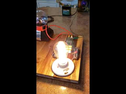
13.2V and .4 A driving a 10Watt 120V LEDComment
-
judging by number, thats COP 2.. however were you able to compare brightness vs it being driven in the outlet power?..Originally posted by ilandtan View PostComment
-
That bulb is illuminated in daylight, not a dark room. But whether it did or didn't, isn't the point. People expectations of some magical circuit to produce OU is not the right direction nor is it easy, or everybody could light a 10W bulb with a plasma globe emissions run from a 12V battery. I did it to show that Don Smith wasn't fake. Fig39.jpg
 Last edited by ilandtan; 03-21-2022, 04:49 AM.
Comment
-
Good example you have there ilandtan. Well done! Very simple example indeed.
Have you tried to connect a ground/earth to the 'secondary' red wire loop ?<< BP Ultimate + Shell-V Power + Allies (opec) = the Ultimate Power Aligators to Suck People`s Blood !-! >>
Comment
-
I got "Don Smith device version 2" fully working. Measured input 0.3W. On receiving coil generates 28 watts each. 3 linearly 84 watts. If you are interested about details, send me a message. I have analyzed all the physics and mathematics behind the device.Comment
-
Sir
we have many good open source builders who would cherish the opportunity ,
tried sending a message,not sure it went through
chetkremens@gmail.com
with gratitude
Chet KIf you want to Change the world
BE that change !!Comment
-
Hi Pecado, I have PM you, but I am not sure if it made through. I am the collector and protector of free energy ideas and I have a linkpage at: http://gratisenergi.se/free.htmOriginally posted by pecado View Post
and I have updated my Don Smith page at: http://gratisenergi.se/donsmith.htm
If you don't plan to massproduce your Don Smith device I would be happy to put up all your information at: http://gratisenergi.se/donsmith.htm
Please send your information to hermesatar@yahoo.com or hermes@gratisenergi.se
Best Wishes, HermesComment
-
I have yet to receive any reply…
Hermes ,you should add Beyondunity.org to your list ,
As a newer open source builders venue in Europe ( global membership)!
we need all the open source help we can get !
respectfully
Chet K
If you want to Change the world
BE that change !!Comment
-
In addition to device 2, I am same time building Don Smith device 3. I have understood that it uses Barker & Williamson coil 3064 Inductance: 32.0 microHenrys, coil length: 10 coil diameter: 3 turns per inch: 4, wire size: 12 AWG.
Rick Friedrich said that it might be different size: What really matters is to understand fully all the concepts.
I have myself calculated it according to the information provided:
height_of_coil =
7.62 cm
length_of_coil =
25.4 cm
distance_between_wires =
0.635 cm
wire_length_one_turn =
23.9474 cm
lenght_of_the_whole_wire =
957.8943 cm
Equation:
wire_length_one_turn = sqrt(distance_between_wires^2 + (height_of_coil*pi)^2)
lenght_of_the_whole_wire = 40 * wire_length_one_turn
I made the coils myself because there wasn’t available this coil when I started
"Main coil" (coil L2)
capacitance = 0.000000047 Farads = 0.047 microFarads
inductance = 0.0000126 Henrys = 12.6 microHenrys
resonance = 1/(2*3.1415926*sqrt( 0.0000126*0.000000047 ))
resonance = 206.8168 kHz
206.8168 kHz x 144 = 29.781 Mhz (related to wavelength, speed of light in copper)
206.8168 kHz Devided by 6 (3, 6 and 144 numbers work great)
operating frequency: 34.469 kHz
What about making it resonate in about 135 kHz. Just more capacitance.
If you do it without red wire, the frequency 12.5 kHz also could be used.
I get 7 amperes peak with the 1/4 red coil of the length 239,47 cm with 11.55 kHz. The voltage is same time 200V even without ground connection.
standing wave: 3 (1 and half), 6 (double), 9 (0)
1, 4, and 7 are compressing harmonies (positive), or (4 7 10 is the same thing) 10 reduces to 1
2, 5, and 8 are expanding harmonies (negative))
Fibonacci: 1 2 3 5 8 13 21 34 55 89 144
144 can be devided with 3, 6 and 9. This also important.
Good information about harmonics:
https://www.electronics-tutorials.ws...harmonics.html
Series Resonance Circuit
https://www.electronics-tutorials.ws...resonance.html
I have unwinded the coil on the center the and connected from the center. That is the reason for the inductance about 12.6 microHenrysLast edited by pecado; 08-14-2023, 08:44 PM.Comment
-
For the device 2, I use coils that has wire length about 990.68 cm and inductance of 150.95 microHenrys. They are from: https://www.r-charge.net/Extra-Induc...ase_p_338.html
I use frequency:
capacitance = 0.000000000180 Farads = 180 pF
inductance = 0.000150 Henrys = 150 microHenrys
resonance2 = 1/(2*3.1415926*sqrt( 0.000150*0.000000000180 ))
968.5861 kHz
Got it work in:
around 930 kHz
The coils also work really well with 150 pF capacitors.
I use same frequency from start to end. It is the easiest way. Other way is to use harmonies, partials, differential tones.
However, the receiving coils can be pure chords (in musical terms) of the center
The best book about the differential tones and harmonics is On the Sensations of Tone, Hermann Helmholtz from 1800'sLast edited by pecado; 08-15-2023, 08:31 AM.Comment
-
The following links have helped me do the right calculations. I count everything and then combine. This makes working much easier and it is much safer. It is important that the frequency has an accuracy of about 3 significant digits. You get much better efficiency. Therefore, the wire length must be exactly the designed length and you can measure several capacitors and choose the ones with the right value:
Series resonance:
https://www.electronics-tutorials.ws...resonance.html
Parallel resonance:
https://www.electronics-tutorials.ws...resonance.htmlLast edited by pecado; 02-21-2023, 10:43 PM.Comment
-
Honestly, I have got best hints from https://www.r-charge.net/Renaissance...it-_p_305.html and https://www.r-charge.net/resonance-i...it-part-2.html.
This book explains the best the electric fields and some fundamentals of free energy in really good way. There is one small error (Nikola Tesla 's equation): Research in Solid State Free energy generators (latest version - working here).docx. I call it 723 pages book
The rest I have figured by myself just by reading a lot different literature.Last edited by pecado; 02-21-2023, 10:30 PM.Comment
-
To get "Don Smith device 3" fully working, it is much easier to test first with smaller device (also that you don't hurt yourself) with the bifilar coil (L2 with CW and CCW rotation winding matching single coil in Resonance Induction kit 1) included in: https://www.r-charge.net/resonance-i...it-part-2.html.
Quote from the link:
"This is the next addition to the Resonance Induction Coupler Kit (R.I.C.K.) that adds more parts downstream to make a testing bed to more safely learn how to make Don Smith magnetic resonance energy systems, specifically Earth Electrical System II."
I have got lot of good information from this kit and I have got also 1/4 wave with red wire working. It has a lot of parts and the value of the information and parts is much than $250. And this bifilar coil can be 100 % sure excited with much lower frequencies by utilizing harmonics or differential tones.Last edited by pecado; 02-23-2023, 06:35 AM.Comment
-
For small Don Smith Device 2:
I am using this for accurately measuring amperage
Tekbox tbcp1 RF current probe
Max. primary current (DC – 400 Hz): 80 A
Max. primary current (RF): 3 A
10 kHz - 250 Mhz
(The amperate is calculated from the voltage measurement according to the chart in the manual)
You can it, for example, from here:
https://iosignal.fi/?s=rf&submit=Search
Now there is new models that accept thicker wire with thick plugs and the frequency range goes from 1kHz to 800 Mhz. This is the absolute the greatest way to measure RF amperage.
I am using this for accurately measuring voltage 0 - 20000 V:
Testec TT HVP 15HFLast edited by pecado; 03-21-2023, 08:21 PM.Comment
Comment