This forum is preserved as a permanent archive. The community continues at eMedia Press.

Announcement

Collapse
No announcement yet.

Future Energy hydroxy cell

Collapse
X
 
  • Filter
  • Time
  • Show
Clear All
new posts

  • lamare
    replied
    Originally posted by Farrah Day View Post
    How does your idea that resonance can be maintained fit in with the pendulum analogy?
    Ok, think of it as push the pendulum like you would push a child sitting on a swing.

    Only don't push continously, but throw a pile of balls one after the other onto the back of the child during the time the pendulum is in the upper "dead" position and the lowest point at the bottom....
    Leave a comment:


  • Farrah Day
    replied
    So, you can't treat the WFC as a simple resistor if you managed to create an electrolytic capacitor inside your tubes and you can't treat it as a simple capacitor if you manage to get ions inside your fluid into some kind of resonance....
    My main argument to this is that the electrolyte (or water) in not an insulator, and two metal plates with a conductor in between is never going to be a very effective capacitor, just a non-linear resistor.

    Leave a comment:


  • lamare
    replied
    Originally posted by grizli View Post
    Meyer series LC resonance circuit can ONLY resonate at SINGLE frequency...
    So seems that puharich way and Meyer ways are different ?
    Electricaly those higher harmonics are filtered by series LC circuit that produce sine current at the capacitor (cell) and SQUARE voltage on the capacitor (cell)
    so cell is basicly capacitor + low resisntce resistor ALL in one...
    hmm..
    Not only that, it is also an inductor if you manage to get the ions inside the fluid into some form of resonance.

    Now you probably understand why Electrical Engineers hate high frequencies. It is because you have to take all these so called "parasitic components" into account. Even a piece of wire has a capacitance *and* an inductance and at some point, you have to account for that.

    So, the main resonance will be determined by the coils and the capacitance of the WFC, but also by the self-capacitance of the coils.

    Beside that, there can be all kind of parasite components that start to vibrate in ways you don't want them to, so you do not get one "pure" harmonic resonance, but some kind of mix of the different frequencies all the different components like to vibrate at.

    Leave a comment:


  • Farrah Day
    replied
    OK Lamare, I'm not particularly following your line of reasoning here, but I'll give it further thought.

    However, if we consider something simple like the resonant frequency of a pendulum, resonance immediately stops once the pendulum is prevented swinging past it's bottom position. Surely this is effectively what halfwave rectification does. Once we eliminate the reverse swing, we destroy the cycle of oscillation and hence resonance.

    How does your idea that resonance can be maintained fit in with the pendulum analogy?

    Leave a comment:


  • lamare
    replied
    Originally posted by Farrah Day View Post
    Meyer never once talks about the dielectric layer on the stainless steel, and we know from experimenting that the chromium oxide does not prevent current flow as you would expect from an insulative coating.

    I'm not saying that it does not play some small part, just that it does not appear to be any kind of electrical insulator, hence in reality will incur little or no voltage drop.

    But these are all long standing issues that arise on a regular basis, when people talk about very high voltage drops across the cells in a WFC, but with little or next to no current flow.
    I'm not saying there is/should be a dielectric layer on the stainless steel, only that the tubes are capacitors to a certain extent, whatever way you look at it. If they would be in the air, you would be talking about a capacitance in the order of maybe 100 pF. If a suitable dielectric layer is formed, you are talking 10s to 100s of uF.

    Then there's the ions in between the plates. If these move, there is a current and therefore a magnetic field, depending on the movements of the ions and the frequency as well. If there is some form of resonance inside the fluid at something like a few kHz, you definately get electromagnetic waves also, which end up in your coils.

    So, you can't treat the WFC as a simple resistor if you managed to create an electrolytic capacitor inside your tubes and you can't treat it as a simple capacitor if you manage to get ions inside your fluid into some kind of resonance....

    Leave a comment:


  • Farrah Day
    replied
    Originally posted by grizli View Post
    TUBE is not fork and does not resonate that way ... its probably longitudinal sound wave along tube metal .. and holding it does not change frequency .. I tested and proved to myself.. holding tube makes sound shorter in time and higher harmonics are dampened... more to say base harmonics is left untouched..
    Tried with different tubes.....
    It's all sound waves isn't it, and the ringing sound we hear is the item oscillating at it's resonant frequency.

    I don't understand what you mean by base harmonics? Harmonics surely refer to frequencies in multiples higher than the fundamental frequency.

    If something resonates at 2kHz, you can't have a harmonic of 500hz... can you? Or when you say base harmonics, do you mean fundamental frequency?
    Last edited by Farrah Day; 09-14-2010, 06:22 PM. Reason: wrong word: replaced harmonics with frequency

    Leave a comment:


  • lamare
    replied
    Originally posted by Farrah Day View Post
    Surely you can't achieve a state of resonance after halfwave rectification has taken place!
    Oh yes, you can!

    Study the wave forms by Puharich! The rectifier rectifies the carrier wave, on top of which is the signal that your coils resonate at!

    So, let's say your coils resonate at 10 kHz and you use a carrier wave of 100 kHz. Then the rectified carrier wave gives you 10 unidirectional pulses to your coil for every half swing they make. The other half of the swing, there should be no pulse....

    Leave a comment:


  • Farrah Day
    replied
    The diode is his (half-wave) rectifier.....
    Lamare, yes, I can see that. The point I was trying to address is that surely the diodes very presence will prevent electrical resonance. Surely you can't achieve a state of resonance after halfwave rectification has taken place!

    Meyer never once talks about the dielectric layer on the stainless steel, and we know from experimenting that the chromium oxide does not prevent current flow as you would expect from an insulative coating.

    I'm not saying that it does not play some small part, just that it does not appear to be any kind of electrical insulator, hence in reality will incur little or no voltage drop.

    But these are all long standing issues that arise on a regular basis, when people talk about very high voltage drops across the cells in a WFC, but with little or next to no current flow.

    Leave a comment:


  • grizli
    replied
    Originally posted by lamare View Post

    As far as I can tell, there are two ways to prevent these unwanted and expensive disturbances to reach your driving circuit:
    1. Use a high-pass filter, as I explain in my article (linked below).
    2. Match the resonances in your WFC to the resonances in your driving coils, so they resonate all at one and the same frequency (or at least harmonic to one another). Then you don't get these "beat" frequencies and so you don't have to pay the price of having your dipole, your voltage source, killed by the beat....

    IMHO, option 2 would be the hard way to do this....

    Meyer series LC resonance circuit can ONLY resonate at SINGLE frequency...
    So seems that puharich way and Meyer ways are different ?
    Electricaly those higher harmonics are filtered by series LC circuit that produce sine current at the capacitor (cell) and SQUARE voltage on the capacitor (cell)
    so cell is basicly capacitor + low resisntce resistor ALL in one...
    hmm..

    Leave a comment:


  • grizli
    replied
    Originally posted by rick123 View Post
    I agree with FD, I must also be missing something Griz, please explain.

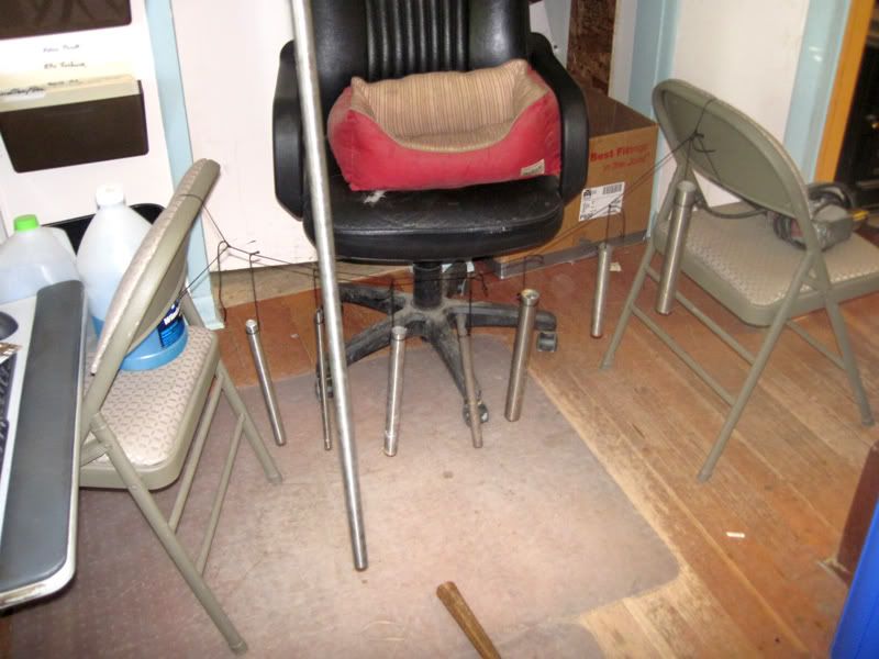
    I spent a bit of time this weekend recording the frequencies of various tubes. None of my tubes fall under 1k hz. most come in around 2k the larger diameter (1.5 inch) around 5k. The thinner the wall the higher the pitch.

    Not a very good pic but here is what I was doing. Hanging different tubes, (clothes line style) and recording the tones with my computer mic.

    And ?

    I also claim that base harminic is NEVER as low as 50-100Hz as Fred claims....

    I just say when you hold tube firmly in hand at the bottom (Fred glues all tubes in epoxy at the bottom) and when tube hangs freely base harmonics is practicly the same..

    Leave a comment:


  • grizli
    replied
    Originally posted by Cloxxki View Post
    The background noise took up most of the display, it seemed. Perhaps our ears ar playing tricks on us? I too hear a rather clearn high-pitch tone, but I see the low-pitch peaks also. Might those be the strike rather than the ring?
    First of all iphone electret mic cant record under 100Hz...

    All that below 100Hz seems like hum

    Originally posted by Farrah Day View Post
    I don't want to argue for the sake of it with a Grizli, but lets look at it this way.

    If you set a tuning fork in motion, it wll vibrate at it's resonant frequency, the frequency that requires the least energy. But the instant you touch a prong or prongs you will dampen the resonant action by effectively altering the physical characteristics of the tuning fork. The tuning fork has become metal tuning fork mass and your mass!

    The resonant frequency of anything will change the instant you alter it's mass, which FF is effectively doing by gluing the tubes into a vessel, so I'm not sure why you would say I'm wrong.

    Perhaps you can elaborate on yours tests?
    TUBE is not fork and does not resonate that way ... its probably longitudinal sound wave along tube metal .. and holding it does not change frequency .. I tested and proved to myself.. holding tube makes sound shorter in time and higher harmonics are dampened... more to say base harmonics is left untouched..
    Tried with different tubes.....

    Leave a comment:


  • lamare
    replied
    Originally posted by Farrah Day View Post
    Well, I see the WFC itself more as a non-linear resistor, but I'm sure at certain frequencies there will be a certain value of capacitance. However Lamare, where then does Meyer's pulsed DC and indeed his blocking diode fit into the grand scheme of things?
    The diode is his (half-wave) rectifier.....

    As for capacitance: if a dielectric layer is formed on one (or both) of the tubes, you would get an electrolytic capacitor, which could easily reach a capacity of several 100 microFarads. But you concluded that yourself too:


    Aluminium, just like stainless steel already has a protective oxide coating, that's why they are both relatively inert to corrosion in air and water under normal circumstances.

    Wet electrolytic capacitors were - and still are - an intriguing design because designers made the anode to have the greatest surface area possible, and no matter how complicated the anode design, it did not need a correspondingly complicated cathode. An electrolytic solution became an extension of the metal cathode container. Also the very thin (microns) oxide layer on the anode made for a high capacitance.

    If we are not careful all we will achieve is the fabricating of a large electrolytic capacitor. The science does need thinking through.

    The wet electrolytic capacitors described above did generate some hydrogen, but this was not by design and was simply due to leakage current. And what H2 did evolve was of course generated by everyday electrolysis action.
    Of course, at that moment, at least I still thought the secret was to be found in the presence of a polarized dielectric on your tubes, but that does not mean you cannot easily end up wit a large electrolytic capacitor. When you use aliminum, you can almost count on that. When you use SS, I don't really know, but it certainly seems possible.

    How^H^H^H Anyway, you can test wether or not your tubes have a significant capacitance pretty easily. You build a simple 555 circuit, like this:

    LM555 Timer Circuits


    And then you use your WFC as the capacitor shown in the schematic. Then you can calculate the value of the capacitor using the formula shown. And you can also easily compare the behavior of your WFC with that of some standard capacitors. I did this some time ago when I was experimenting with an electrolytic capacitor made of an aluminum tube and a copper plate submerged in soda. It had a capacitance of about 100 uF.


    Update: also see:
    Baking Soda Variable Electrolytic Capacitor. - "Baking Soda Variable Electrolytic Capacitor. - While experimenting with the borax rectifier, I found that everything also worked well using a baking soda solution (1 tablespoon baking soda to 2 cups of tap water). The aluminum strip shown in the above picture was cut from a piece of aluminum pie plate. I also discovered, with either the borax or baking soda rectifier, that it acted like a large capacitor as well as a rectifier when biased in the reverse direction. I had built a homemade electrolytic capacitor. I decided to do some experimenting and measurements to see what capacitance values could be obtained. I found it easy to get large values up to 100 uf. Since the capacitance is based on a thin film of aluminum oxide that forms on the aluminum plate, the capacitance can be varied by sliding the plate in or out of the baking soda soda solution. By using a wedge shaped piece of aluminum, I was able to get continuously variable capacitance ranges of up to 5000 to 1."

    Borax or Baking Soda Rectifier and the glow. - "How To Observe The Glow From A Borax Or Baking Soda Rectifier."
    Last edited by lamare; 09-14-2010, 10:49 AM. Reason: typo. Farards should be microFarads

    Leave a comment:


  • Farrah Day
    replied
    Well, I see the WFC itself more as a non-linear resistor, but I'm sure at certain frequencies there will be a certain value of capacitance. However Lamare, where then does Meyer's pulsed DC and indeed his blocking diode fit into the grand scheme of things?

    Leave a comment:


  • lamare
    replied
    Originally posted by Farrah Day View Post
    I'm not buying into this tuning stuff at all. The minute you glue the tubes into the vessel, any previously individual resonant frequencies become irrelevant as the tubes then become part of a larger whole. It makes little sense to me.
    Let's see what we can say about this.

    If you look at what Meyer and Puharich did, then from an EE point of view, they have their load in between two coils, which are most likely resonating. But resonating such that the overall resonance, which would be over the whole load train (coil 1 - WFC - coil 2), is such that you have high voltage, low current at the driving terminals of your coils. And that would be so called half or full wave resonance.

    Now if you can consider your WFC to be a nice linear capacitor, then you would basically have a simple LC oscillator with a single resonance frequency.

    How^H^H^H But if your WFC is not a nice linear capacitor, like when you have ions moving back and forth, you get interference patterns between what we might call the "LC" resonances and the resonances in your electrolyte, whatever those may be.

    The problem is that these resonances in your electrolyte, insofar electrically relevant (ions), also end up in your coils. Whenever you mix two waves of different frequencies, you end up with the so called "differential frequencies" or "beats" as the are called in acoustics. See for example:

    Beat Frequencies in Sound - Succeed in Understanding Physics: School for Champions

    If you add two waves of slightly different frequencies, the resulting amplitude will vary or oscillate at a rate that is the difference between the frequencies. That beat frequency will create a beat envelope around the original sine wave.


    Since the frequencies of the two sounds are so close, you would hear a sound that is an average of the two. But you would also hear the modulation of the amplitude as a beat frequency, which is the difference between the initial frequencies.
    This principle is used all over in radio and signal processing and is called heterodyne:
    Heterodyne - Wikipedia, the free encyclopedia

    In radio and signal processing, heterodyning is the generation of new frequencies by mixing (multiplying), two oscillating waveforms. It is useful for placing information of interest into a useful frequency range following modulation or prior to demodulation. The two frequencies are mixed in a vacuum tube, transistor, diode, or other signal processing device. Mixing two frequencies creates two new frequencies, according to the properties of the sine function; one is the sum of the two frequencies mixed, the other is their difference

    So, if we can assume that whatever resonances are taking place in the WFC generate electrical signals, because there are ions in the electrolyte if the electrolysis is basically Faraday-like, then you get these differential frequencies in your coils as electrical disturbances. And it is these disturbances that eventually reach your driving circuit if you don't do anything to prevent that. And that means you don't have your nice "high voltage, zero current" situation at the terminals of your coils anymore and you will have to pay for that.

    As far as I can tell, there are two ways to prevent these unwanted and expensive disturbances to reach your driving circuit:
    1. Use a high-pass filter, as I explain in my article (linked below).
    2. Match the resonances in your WFC to the resonances in your driving coils, so they resonate all at one and the same frequency (or at least harmonic to one another). Then you don't get these "beat" frequencies and so you don't have to pay the price of having your dipole, your voltage source, killed by the beat....

    IMHO, option 2 would be the hard way to do this....
    Last edited by lamare; 09-14-2010, 09:39 AM.

    Leave a comment:


  • Farrah Day
    replied
    YouTube - Fast Freddy's Update 7

    He could have simply stated that the tube ends were machined in the previous videos, which now, for some reason, seem to have been removed. Yet another very disappointing instalment - though I suppose great if you want to get to know his friends and family.

    What part does that $1100 dollar 'puk' - I think he called it - of SS he was slapping, play in all this I wonder?

    At this rate it will be well past Christmas before he discloses anything of any real value... if he ever does!

    Leave a comment:

Working...
X