-
Well you're not alone there eclipz. Yet another totally pointless video. What is anyone surposed to take away from that? What the hell is he doing?Originally posted by eclipz View Post
He might as well be showing us his 'brother' making the coffee. I've got a horrible feeling it's all down hill from here!Leave a comment:
-
Leave a comment:
-
Now I see what you were getting at Lamare.Originally posted by lamare View Post
The problem I see with what you are suggesting is that, I for one, have never noticed any such sudden unusual, rush of current flow across ss electrodes that I would expect to see if a dielectric suddenly failed.
In fact even when applying some very high voltages, I've never seen the current rise other than in proportion to the applied voltage.
In a normal insulative dielectric such as, let's say a plastic film, leakage current is due to some mobile electrons within that dielectric material itself, is it not? What I'm suggesting, and indeed what I believe is far more likely, is that the oxide layer in the case of the metals is more like a mesh that allows the small electon to pass unobstructed, but will prevent the passage of the much larger oxygen atoms or molecules. I'm also suggesting that at extremely heavy currents this mesh can tear, effectively creating a hole big enough for an oxygen atom or molecule to reach the underlying metal.
If you think about it the mesh scenario works quite well. Initially, when exposed to air or water, the oxygen would react with the bare metal to form this oxide layer. However, as soon as the oxide layer has covered the metal to the point whereby further oxygen molecules can no longer reach the bare metal, then the process would halt. This layer would surely only have to be a molecule thick to prevent further oxygen reaching the metal, but as such would surely be no obstacle to the electron.Last edited by Farrah Day; 09-16-2010, 03:53 PM.Leave a comment:
-
Couldn't have put it better myself!I think the most important questions regarding Meyer and Puharich is: can we trust their observations and measurements? I think we can to a large extent. The question wether or not we can trust their interpretation of things is a completely different question, but there is nothing that stops us from making our own interpretation of their observations and measurements
Valid questions indeed Lamare. I would think this more likely to be a cavitation effect, whereby the bubbles would actually be water vapour.The rim 4 is the housing of the WFC. So, why does he say these originate at the electrode rim, while he draws them a bit away from that??
And how does he know these are hydrogen bubbles just looking trough a microscope? Why aren't these hydrogen + oxygen??? I mean, if the water molecules are shattered then we should get both, right?
Regarding the protective oxide layer. Most oxides are poor conductors of electricity, and indeed the forced build up of calcium carbonate on the cathodes in my experiments have shown it to be of extremely high resistance - if I've managed to get any value of resistance even to register, that is! Yet charges seem to exchange at the electrode as if the mineral coating was not even there.
Of course a natural oxide protective coating also applies to copper, silver, gold, aluminium and others along with our stainless steel. All have a very effective protective oxide layer that prevents further oxidation and hence corrosion of the underlying metal. And all - particularly in the case of copper and silver - are very good conductors of electricity. So I think we must assume that the electron, being so much smaller than a molecule (or atom) of oxygen, can navigate through the oxide layer to reach the metal underneath, whereas under normal conditions an oxygen molecule can't.
Only when vast amounts of electron current flow occurs does this oxide layer start to fail and allow the ingress of oxygen - which of course would be right at hand on the anode to react.
This very reaction would result in less oxygen being evolved as gas, as instead we get rust. We would also no longer have a stoichiometric volume of hydrogen and oxygen. Thought whether this ultimately plays any part in terms of combustion and energy release is unknown and open to debate.Last edited by Farrah Day; 09-16-2010, 01:18 PM.Leave a comment:
-
I think the most important questions regarding Meyer and Puharich is: can we trust their observations and measurements? I think we can to a large extent. The question wether or not we can trust their interpretation of things is a completely different question, but there is nothing that stops us from making our own interpretation of their observations and measurements.Originally posted by Farrah Day View Post
I found a few very interesting details in Puharichs stuff:
Andrija Puharich: Water Decomposition by AC Elecrolysis >
First of all, he used a dielectric in between is electrodes:
The space between the two electrodes contains two lengths of tubular Pyrex glass, shown in Figures 2 and 3. The metal electrode surface in contact with the water solution are coated with a nickel alloy.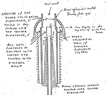
I was astonished to read this:
There is an `Open Circuit` reversible threshold effect that occurs in Component III due to water polarization effects that lead to half wave rectification and the appearance of positive unipolar pulses;So, that's where is rectifier is! In his WFCA secondary effect of the change in the RC constant of water on the wave form shows up as a full half wave rectification of the carrier wave indicating a high level of polarization of the water molecule in tetrahedral form at the outer electrode.
And that is a well known effect:
A blue-green glow has been observed on electrodes of high voltage electrolytic cells and electrolytic rectifiers. [1] [2] Electrodes to create the blue-green glow can be made from metals like Ni, Zn, Ti, Al or Zr that form insulating oxides. The glow has been created in cells containing a weak electrolyte like Pickling Lime (CaO), Baking soda, sodium metasilicate, or acetic acid, by gradually increasing the AC voltage through them typically to 200 - 400 V AC. Zn can only be conditioned to about 76 volts. .
In the early days of amateur radio, the dc plate voltage power supply for the transmitter, was often made using homemade rectifiers. From what I have read, these rectifiers would usually consist of an aluminum and lead electrode in a jar of Twenty Mule Team Borax solution. Borax is another name for sodium tetraborate. The aluminum becomes the cathode after a forming process of applying some ac current through the rectifier. Often, many jars were used in order to accomodate high voltages. It has been reported from various sources, that these rectifiers would also emit a faint glow when in operation.
Let me just say that based on this, Meyer and Puharich's interpretation of what happens inside the water does not convince me at all. Another thing that points in this direction is the desired frequencies reported. I couldn't find anything by Meyer himself, but found this:
Stanley Meyer: Water Fuel Cell
And Puharich:here are two primary frequencies that produce the best results. They are: 14,372 Hz and 43,430 Hz. The former is about 50% more efficient, but it seems that just about any frequency between 9 KHz and 143,762 KHz works quite well. (1) This is because the nature of the wave form ( a spike ) is rich in harmonics and one of them is bound to be close to one of the two primary frequencies.
Use of permanent magnets may also increase efficiency. I'll give you the outcome of that attempt in my next letter along with the plans for what I hope to be a much improved version.
Note: Sub-harmonics of the two primary frequencies at which dissociation will occur:
43430 Hz 143762 HZ
SUBHARMONIC SUBHARMONIC
1st 21715 HZ 1st 71881 HZ
2nd 14476.67 HZ 2nd 47920.67 HZ
3rd 15517.5 HZ 3rd 35840.1 HZ
4th 8686 4th 28752.4 HZ
*1500 VOLTS IS THE MINIMUM REQUIRED FOR MOLECULAR RINGING TO BEGIN.
These don't really match, which suggests that the desired frequencies reported actually tell more about the construction of the cell then about the way the electrolysis is performed.The wave form now automatically shifts to a form found to be the prime characteristic necessary for optimum efficiency in the electrolysis of water and illustrated in FIG. 11. In the wave form of FIG. 11, the fundamental carrier frequency, fc = 3980 Hz., and a harmonic modulation of the carrier is as follows:
1st Order Harmonic Modulation (OHM) = 7960 Hz.
2nd Order Harmonic Modulation (II OHM) = 15,920 Hz.
3rd Order Harmonic Modulation (III OHM) = 31,840 Hz.
4th Order Harmonic Modulation (IV OHM) = 63,690 Hz.
I think the electrolysis is pretty normal and the key is into how to get the power to do it, which has everything to do with the electric waves and (ion) currents going trough the fluid.
The final thing that is very interesting in Puharich's is this, "an illustration of pearl chain formation":
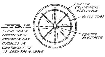
This shows his WFC from above and this is what he says about this:
The rim 4 is the housing of the WFC. So, why does he say these originate at the electrode rim, while he draws them a bit away from that??What is believed to be happening in this IV OHM effect is that each of the four apices of the tetrahedron water molecule is resonant to one of the four harmonics observed. It is believed that the combination of negative repulsive forces at the outer electrode with the resonant frequencies just described work together to shatter the water molecule into its component hydrogen and oxygen atoms (as gases). This deduction is based on the following observations of the process through a low power microscope. The hydrogen bubbles were seen to originate at the electrode rim, 4', of FIG. 3. The bubbles then moved in a very orderly `pearl chain` formation centripetally (like the spokes of a wheel) toward the center electrode, 1' of FIG. 3. FIG. 12 shows a top view of this effect.
And how does he know these are hydrogen bubbles just looking trough a microscope? Why aren't these hydrogen + oxygen??? I mean, if the water molecules are shattered then we should get both, right?
Update:
Compare the "pearl chain" formation with this:
CYMATICS - Visible Sound
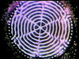
More on Cymatics, including some video's here:Dr. Jenny took the idea of the Chladni plate but went on to excite it using precisely measured vibrations (cps - Hertz) and amplifications (volume) via a piezoelectric effect using a crystal oscillator and then to cover the plate with various substances and finally to document his results in both photographs and films. He researched this phenomena for 14 years. The results are truly awe inspiring, breathtaking, most inspiring and enlightening.
The Wave Phenomena of Cymatics
I have seen some of the video's by Jenny. Very interesting and entertaining!Last edited by lamare; 09-16-2010, 08:28 AM.Leave a comment:
-
Farrah
A cranium capacitor was my attempt at humor as well.
To Lamare and All: Thanks for the response. I have stared my thread http://www.energeticforum.com/renewa...ead.php?t=6400
Thanks again
SmallengtechLeave a comment:
-
Yes, sorry SmallT, that was an attempt at humour on my part.Originally posted by smallengtech View Post
Lamare, I concluded long ago that Puharich is far more credible than Meyer in terms of the science and electronics. In fact I have always considered Meyer's interpretations of the science and his technical briefs as utter gibberish. In my eyes, if anything, Meyer's science - or lack thereof - only adds misinfo and confusion to the mix.
That said, we surely have to take a leap of faith with Puharich. I believe that he suggests that the angle of the hydrogen bonds on the oxygen atom in a water molecule are altered to in effect become more rigid, less flexible and so more easily broken. But how much faith can we put in his interpretation of things?
I have to say though, I would be a lot more comfortable with Puharich if he hadn't become involved in parapsychology, and the likes of Uri Geller. For me at least, this gave me doubts about his credibility as a serious scientist. Spoon-bending, mind reading and teleportation.
Leave a comment:
-
Well If fast Freddie figures out how to put this in his truck,he'll be in like Flynn
post 1435 [a must see]
ChetLeave a comment:
-
Hello smallengtech! My guess is this topic is primarily about Fast Freddie's work and since it is a water fuel cell design, Meyer's name gets mentioned. Start a new thread and let us read your ideas.Leave a comment:
-
Hello everyone
I have been lurking around the forums for over a year and have learned a few things by reading different post by all of you. I would consider myself to be a novice when it comes to electronics but have been a maintenance tech on outdoor power equipment to heavy jets for 15+ years. I hope that I might be able to contribute some ideas in regards to Meyer's system based on what he says in his tech brief. What I do not know is if this would be the proper thread to post in considering the topic or if I should start a new one.
Farrah
The schematic that Lamare posted is Puharich's circuit for helping the hearing impaired to be able to hear tones and in turn speech. Not for electrolysis of the cranium capacitor.
SmallengtechLeave a comment:
-
I have been briefly trough Puharich's stuff over here:Originally posted by Farrah Day View Post
Andrija Puharich: Water Decomposition by AC Elecrolysis >
His patents are also at my server: Bestandsoverzicht van /pdf/Patents/Puharich/
From what I read so far and what I saw from his other patents (did a patent search this afternoon) you can tell Puharich is a real scientist, which had proper equipment and also refers to scientific papers. He definately understood resonance, because he used that for curing patients. Something with hearing, etc. So, the basic resonance control circuits came from his medical patents.
He also talks about what electrolyte to use and how that is important to control the resonance inside the water. And he is talking about how the molecule structure of water is changed, based on QM IIRC.
So, this suggests to me Puharich knew what he was talking about and his work is well worth further study.
So, at this moment we have two possible ways to do this.
1. You don't buy the resonance stuff. Then you would go for high currents trough your WFC and thus no dielectric. As thin as possible. And then you would have to optimize your driving circuit and the coils along the way Gray did.
2. You do buy the resonance stuff, or at least want to give it a try. Then you would have to optimize your circuitry such that you get the resonance needed as efficiently as possible. Then Puharich is the one to study and replicate. The only important thing I can see so far to change in his system is to move the rectifier *after* the insulation transformer.Leave a comment:
-
Lamare, I think part of the problem is we really don't know what we want do we? Do we really want the water to resonate? If so why? Irrespective of the claims to knowledge of the reactions and processes by various inventors, all we really have is various interpretations of what is or might be occuring.
I'm not sure this particularly explains anything. I thought we'd covered this. At lower current levels you tend not to see this deterioration, but current is flowing even at very low voltages so the oxide coating must be passing current - the anode must be taking on electrons all the time! It's got to be the sheer amount of electrons that is doing the damage in FF's case.Now things really start to make sense in this part, too. It appears that wat FF is doing, is force a current trough his WFC because the dielectric on his tubes breaks. That explains why his tubes detoriorate, because the protection the dielectric provides works because no electrons can reach the metal inside, so the metal cannot oxidise.
Here's another problem. If we coat the electrodes with a DC impermeable coating, how then do ions exchange charges to become atoms and evolve as gases? They can't so that eliminates electrolysis as we know it... or gives rise to another flaw in our thinking.
All this would be a lot easier if we knew exactly what we were trying to achieve and why. But even after all this time we are still theorising on the behaviour of the WFC.
I've never accepted Meyer's version of high voltage pulling the water molecule apart into its constituent parts as he depicts in his technical brief, and clearly if the voltage resides across a dielectric and that dielectric is not the water, then this is the nonsense I've always suspected it to be.
Incidentally, I've not seen that Puharich schematic before - is that someone's head being electrolysed??Leave a comment:
-
When you apply DC, yes.Originally posted by Farrah Day View Post
But capacitors also act as high pass filters. So, at higher frequencies they act as shortcuts. That is the effect Gray was using, and Meyer as well. So, I was wrong in that Meyer and Puharich should have used couple capacitors. They did, they just were at a place where I didn't see them
Now things really start to make sense in this part, too. It appears that wat FF is doing, is force a current trough his WFC because the dielectric on his tubes breaks. That explains why his tubes detoriorate, because the protection the dielectric provides works because no electrons can reach the metal inside, so the metal cannot oxidise.
So, if you want to get the fluid into resonance and want the electric field to power your WFC, you do want to use capacitative coupling and you do want to make sure your dielectric layer does not break down. So, on the one hand you want large capacitance between your tube and your fluid, and on the other hand you want the layer to be thick enough so it can withstand the voltages you torture it with.
In order to do that, aluminum would be a much better choice for your tubes as stainless steel, because with aluminum we know how to grow dielectric layers with just the right properties. You can grow them electrolytically in a bath with soda, just like when you make an electrolytic capacitor. Only in this case, you want a relatively thick layer on both tubes, so you would grow the layers using AC instead of DC. And if you use the circuitry you intend to use to drive your WFC with, the layer will automagically grow until the optimal thickness is reached...
See the exercise with the soda rectifier over here:
Borax or Baking Soda Rectifier and the glow.
Update: I spent some time collecting some relevant patents, a.o. by Puharich and Meyer. You can find them here: Bestandsoverzicht van /pdf/Patents/
Given that Puharich was a Dr. I think his explanations on how the water can be split will be very close to the truth. After all, he did do this and he did manage to come up with almost the right circuit. He missed only one detail...
Update 2: I also found the schematic of Puharichs AM modulator: Article:Free Electric Energy in Theory and Practice - PESWiki

Update 3: Puharichs water splitting patent can also be read online here:
Andrija Puharich: Water Decomposition by AC Elecrolysis >Last edited by lamare; 09-15-2010, 01:56 PM.Leave a comment:
This forum is preserved as a permanent archive. The community continues at eMedia Press.
- If this is your first visit, be sure to check out the FAQ by clicking the link above. You may have to register before you can post: click the register link above to proceed. To start viewing messages, select the forum that you want to visit from the selection below.


Leave a comment: