This forum is preserved as a permanent archive. The community continues at eMedia Press.

Announcement

Collapse
No announcement yet.

Bedini Ferris Wheel Regauging Motor

Collapse
X
 
  • Filter
  • Time
  • Show
Clear All
new posts

  • Matthew Jones
    replied
    Originally posted by Mark View Post
    Using one wire off the bifilar as the trigger. All 3 coils in parallel. 2200 ohm resistor from collector of mpsa06 to base of MJL21193. 18000 ohm resistor on trigger to base of mpsa06. I just recently removed the resistors from base to emmiter on both 91193 and 21194, no noticeable difference. Resistors are all 1/2 watt. Outputs from both collectors of 21193 & 21194 to full bridge of 1n4007's and 10uf 250v cap back to source. This set up was 25ma 12 volts @ 2310 rpm's.
    I'm still playing with it to see how much lower I can go on input. Any other questions let me know.
    Mark
    Thanks Mark
    Matt

    Leave a comment:


  • cody
    replied
    Got my motor running. From what ive observed so far, i was not quite correct on my guess where the switching was. Ive been getting good results switching before TDC with an attractive pulse. Seems to run the best if the pulse ends right where the coils generated sign wave just starts to decrease, so the pulse ends a little before TDC. Picture of scope shot across coil below of switching. Still more testing to do. I was going to try and use 2 switches and do a bipolar or flip flop type setup, but it seemed to run better with just one switch, i may have had something rigged wrong there. Still need to order proper circuitry, just getting it going with reeds for now.


    Leave a comment:


  • ren
    replied
    John Bedini,

    Im working on my rotor right now and I have a question regarding magnet spacing. Im using the rotor seen here YouTube - DC/AC Magneto

    Its 500mm diameter and HAD 16 magnets, NSNSNS etc. I have knocked out every south magnet, but before I reglue them in I wanted to ask if there will be sufficient spacing between magnets if I convert this to all north? Its a little over 2 magnet spacings between magnets, so it conforms to the monopole standards, but would I be better off using only 8 magnets and having a larger gap inbetween with which to time the recovery?

    I guess what I am asking, is it easier to time correctly with a larger gap between magnets, or can we stick to the average rule of thumb of 2-5 magnet spacings?

    Im really looking forward to getting this up and running.

    Regards

    Leave a comment:


  • Mark
    replied
    Originally posted by Matthew Jones View Post
    How did you wire it up Mark?

    Thanks
    Matt
    Using one wire off the bifilar as the trigger. All 3 coils in parallel. 2200 ohm resistor from collector of mpsa06 to base of MJL21193. 18000 ohm resistor on trigger to base of mpsa06. I just recently removed the resistors from base to emmiter on both 91193 and 21194, no noticeable difference. Resistors are all 1/2 watt. Outputs from both collectors of 21193 & 21194 to full bridge of 1n4007's and 10uf 250v cap back to source. This set up was 25ma 12 volts @ 2310 rpm's.

    I'm still playing with it to see how much lower I can go on input. Any other questions let me know.

    Mark

    Leave a comment:


  • Matthew Jones
    replied
    Originally posted by woopy View Post
    Thanks John for the advice
    so i made it with quite good basic results, please see the video
    I think it is what you suggested , a bipolar switch , is it OK ? or i am wrong ?
    But now i have some question marks, as how to pull back this energy back on the input basis?
    And much more important yet is the timing, as i can see the Led lamp is much more powerfull when the rotor is slow, but when i replace the leds with a DC small motor i only can get some spinning at higher input voltage (about 10 volts or more) and higher RPM ??
    the learning program seems to be long but fascinating
    good luck at all
    Laurent
    YouTube - pulse motor with PMH armature test 2.wmv
    Seems that you should go slower. Same thing happens to monopole if you time it to run too fast the spike drop.
    Your looking for a good spike. And few of them.
    If you set yourself up with a high farad capacitor in the beginning, like a 12 volt 1/2 farad or battery (Maybe) and low farad in the back like you have you can make a cap dump back to the front.

    Thats the cap dumper I was using earlier. It was based on a solid state relay. There are several other ways to do it.
    I am not sure how it would sustain itself but it would defendantly lower your over all draw. The cap dumper is a neat thing. IT puts a new twist on things for sure.

    Also if you do another video I would like to see the draw on the power supply if possible. Just a request.

    Cheers
    Matt

    Leave a comment:


  • woopy
    replied
    Thanks John for the advice

    so i made it with quite good basic results, please see the video

    I think it is what you suggested , a bipolar switch , is it OK ? or i am wrong ?

    But now i have some question marks, as how to pull back this energy back on the input basis?

    And much more important yet is the timing, as i can see the Led lamp is much more powerfull when the rotor is slow, but when i replace the leds with a DC small motor i only can get some spinning at higher input voltage (about 10 volts or more) and higher RPM ??

    the learning program seems to be long but fascinating

    good luck at all

    Laurent

    YouTube - pulse motor with PMH armature test 2.wmv
    Last edited by woopy; 12-11-2010, 10:44 PM. Reason: youtube bug but ok now

    Leave a comment:


  • Matthew Jones
    replied
    Originally posted by Mark View Post
    Hi Chuck
    Can't really see much on that video its too blurry. I've had my 3 pole kit running for a week now on the 1/2 Bedini cole switch. With 12 volts I can run it on as low as 23ma @2170rpm (1 battery set up). With 36 volts 120ma @ 7500rpm.
    Mark
    How did you wire it up Mark?

    Thanks
    Matt

    Leave a comment:


  • gyula
    replied
    Originally posted by John_Bedini View Post
    Woopy,
    Good video nice spike. If you would build the Bi-Polar switch you would be free of that supply. Then it would be easy to tap the energy to the cap and switch it back.
    John B
    Hi John,

    Would like to know whether you meant Woopy could get a self runner when using the Bi-polar switch?

    I assume a rechargable battery would still be needed to replace his power supply and those huge voltage spikes stored in the cap could recharge the battery in the off time, this is how you meant and this process could maintain the starting battery energy state, right?

    If Woopy used a huge value capacitor instead of the battery, charged up first to 8V or so from a separate supply then use it as an energy source or sink, could he receive a few hours operation from it? I mean the COP of this setup is very near to 1 like 0.999.
    Putting this otherwise: the chemical reaction inside the battery may make this setup to have a COP of 1.03 or so, maybe a bit higher but using a huge value capacitor the COP goes just under 1. Are these correct assumptions?

    Thanks, Gyula

    Leave a comment:


  • rosehillworks
    replied
    Thanks John B for your answer. Chuck H thanks for the correction. William

    Leave a comment:


  • Mark
    replied
    Hi Chuck

    Can't really see much on that video its too blurry. I've had my 3 pole kit running for a week now on the 1/2 Bedini cole switch. With 12 volts I can run it on as low as 23ma @2170rpm (1 battery set up). With 36 volts 120ma @ 7500rpm.

    Mark
    Last edited by Mark; 12-11-2010, 03:13 PM.

    Leave a comment:


  • chuck H
    replied
    Originally posted by rosehillworks
    You may have my wife's ph number the last to numbers of hers is 00 mine is 01 other then that thy are the same she is at work so she will not answer sorry for being off topic Thanks William
    @ William. Call was meant for chuck H
    @ JB, Thankyou very much for the help. see video on you tube. next will be timing wheel and Bedini/Cole switch with cap dump. Exciting stuff coming guys/gals...
    YouTube - 1210102253

    Leave a comment:


  • redrichie
    replied
    Jeremy,
    I know your busy with school/ Is it possible to post your drawings in a way I can enlarge them? I would love to see what you drew. Thanks man.

    Leave a comment:


  • Turion
    replied
    The regular bicycle wheel (steel rim) with threaded rod attached and a strip of plastic to form the new wheel works pretty well. The rods (as spokes) are really solid. I used some thin plastic as a temporary wheel to get the spacing right. As soon as it is all done, I will use the thin plastic as a template to drill the holes in the thicker stuff. Probably won't have it all put together until Monday, and then will begin to glue magnets in place, Have my wire ordered, so will begin winding coils as soon as it gets here. This will be about a six foot wheel.
    Last edited by Turion; 04-20-2012, 03:13 PM.

    Leave a comment:


  • Web000x
    replied
    Originally posted by jerdee View Post
    you want to self bias this from the pulse

    I like your line of connections with the Bedini Ferris Wheel Motor. I would have loved to attend the conference but was busy working just to pay bills. Maybe I can save some money and come to the next one.

    This post has really got my attention because it seems to encompass all of the key points that Charles Steinmetz and Eric Dollard discuss as far as understanding the importance of variation in the square root of negative one.

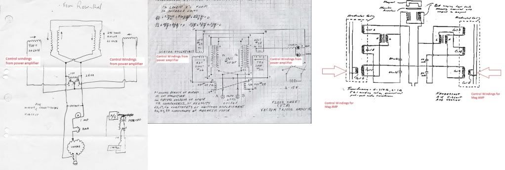
    Sqrt(-1) is representation of capacitance or inductance. Changing the inductance with a mag amp setup like you describe would theoretically allow for excess energy to flow into the system.

    Good work Jeremy!

    Dave

    Leave a comment:


  • John_Bedini
    replied
    Bedini GT3

    William,
    The energy is collected after the trigger, then collected to the capacitors.
    Chuck H will call you in about 15 m
    John B

    Leave a comment:

Working...
X