
spike ?
John B. Is this how it works. Do we switch on as magnets are coming in, switch off before tdc collect the spike let magnets pass collect the spike. Then use collected energy to power the next switch ? Thanks william
-
Bedini GT3
Woopy,
Good video nice spike. If you would build the Bi-Polar switch you would be free of that supply. Then it would be easy to tap the energy to the cap and switch it back.
John BLeave a comment:
-

good work Woopy, that scope is telling something, look at the radiant spike, it looks very good, with that tiny input, i think you have something there.Leave a comment:
-
pmh motor test 1
Hi all
As Jetijs asked me to do a Video of the test pmh pulse motor
here it is
Just for info i elevated the PMH prods something higher so to face the ring magnet on the top of diameter , and it work better than when i center the prods in the center of the ring magnet. Perhaps it is a mean to get "sharper effect as per a superpole" ?
No pretention at all, and always on the hard learning way
Hope this helps
good luck at all
Laurent
YouTube - pmh motor 1Leave a comment:
-
I did some experiments today with a PMH and managed to charge a small iron bar while placed across the u-bolt. What's interesting is that the iron bar does not need to make contact with the u-bolt and can be charged while suspended closely. Once charged if you flip the iron bar (reverse the ends) and charge it again it will go neutral. "Ring twice" may be referring to charge on (create dipole) and charge off (neutral).Originally posted by everyidea View Post
Also I found that using cold roll steel retains more magnetism when charged and neutralizes flat when reversed charged.
EcomanLast edited by Ecoman11; 12-10-2010, 10:56 PM.Leave a comment:
-
Raymond Radus
Found a recent PBS video...
Anyone live near Lucas, KY and want to go tell Chris Radus what he has!!!
Skip to chapter 3 of 4...that's where the video starts. Enjoy and have a wonderful weekend!
Brent
Season 8: Episode 1 | History Detectives | PBS VideoLeave a comment:
-
After reading the Davis manual I noticed that almost all the U motors or generators had rod/axle switches. I wonder if Ed used them too so he could turn his PMH's on and off. Could it have looked like this?
rwAttached FilesLast edited by everyidea; 12-10-2010, 10:09 PM.Leave a comment:
-
-
Bedini GT3
Turion,
Yea, that is right, you can't use this type of core because the magnetic streams do not run one agents the other to form the lock. The tape wound core is in layers and they will repel each other and leak. The only way to work with this energy is with plain old soft iron or cast iron and that is it. But there's more to all this which I can not get into right now. These type cores are designed to loose energy that is why you have them in everything. You may think not but you just saw it.
John B
Originally posted by Turion View PostLeave a comment:
-
As these three YouTube videos relate to ED's work, and as it has been much discussed here, I thought they might be of interest.
YouTube - Transformer core tests part 1
YouTube - Transformer core tests part 2
YouTube - Homemade magnetic amplifiers made from common materials.Last edited by Turion; 12-10-2010, 11:48 AM.Leave a comment:
-
Bedini GT3
John,
Would you please tell us the mounting degrees that you used for the axial coils.
------------------------------------------------------------------------------------------------------
I said I have Ten coils that would make it 36 degrees each.------------------------------------------------------------------------------------------------------
Or have we not made it that far? The axial magnets are at 36 degree spacing correct? one set of the five coils are out of phase with the other but both at 72 degrees each, correct?
---------------------------------------------------------------------
Yes---------------------------------------------------------------------
You told me before that its 2 short pulses (outside coils) and one long one to drive it around (central coil). In your video you stated that EVERYTHING was parallel. So the axial hub is in parallel with the bottom coils but each axial coil is in series with each other?
----------------------------------------------------------------------
Yes a series arrangement switched 5 times.----------------------------------------------------------------------
In my mind I see the the following, please correct me so I can get a clearer picture: the wheel is started into rotation. The axial is in neutral territory due to coil spacing.
---------------------------------------------------------------------
Yes
---------------------------------------------------------------------
The right coil fires first, the wave and spike are sent to the cap pulser which fires just right and dumps copious amounts of energy into batteries.
---------------------------------------------------------------------
No
---------------------------------------------------------------------
. A piece of that charge is sent to the axial motor now that the rotation has brought us into regauging territory. so the first series of n/s coils are energized (PMH) and we are pulled through the first coils lenz. Then the left coil fires, again to cap pulser to batteries. followed by the reguage and flipping of the poles on the axial to counter the lenz of the left coil. so the 2 short pulses are countered by the regauging motor no loss of rotational energy correct?. Then the center is fired a long duration due to the flux shaping and a large spike is sent to the cap pulser and sent to batteries to charge. the axial is in "neutral' territory again temporarily due to coil spacing and is carried through by flywheel rotation and the long stroke of the center coil.
----------------------------------------------------------------------
No First pulse is sent to all coils and they repel then the re-gauge takes place. Very little power is returned to primary battery here. as the power, long flash is when the energy is re-gauged to suck all the magnets in. then it starts over again. then what is waste power goes to the cap. The Starr Motor has nothing to do with running of the machine it only acts as a generator if the macine is in run mode then it's circuits are off. It's just for Idling the machine.----------------------------------------------------------------------
I would also like to add I appreciate the way you are teaching us. I am really starting to understand things I feel. Now I see why you are doing it this way. With the people participating in this thread we are actually learning. Other SG groups and ways of doing it make for a lot of chaos and bickering. No one wins that way and the people cant screw it up and say it doesnt work even though "they followed the directions". I am gathering materials to get underway. I am trying to get a flow chart to see if I really do "get it".
Thanks again
----------------------------------------------------------------------
I hope your all learning something here, but do not give up just yet more to come on ED
John.----------------------------------------------------------------------
Originally posted by redrichie View PostLeave a comment:
-
Slave Coils as Power Windings
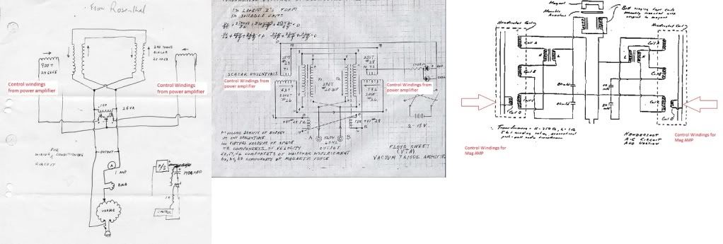
you want to self bias this from the pulse
Leave a comment:
-
Yep your reed will not make it terribly long.
John,
Would you please tell us the mounting degrees that you used for the axial coils. Or have we not made it that far? The axial magnets are at 36 degree spacing correct? one set of the five coils are out of phase with the other but both at 72 degrees each, correct?
You told me before that its 2 short pulses (outside coils) and one long one to drive it around (central coil). In your video you stated that EVERYTHING was parallel. So the axial hub is in parallel with the bottom coils but each axial coil is in series with each other? In my mind I see the the following, please correct me so I can get a clearer picture: the wheel is started into rotation. The axial is in neutral territory due to coil spacing. The right coil fires first, the wave and spike are sent to the cap pulser which fires just right and dumps copious amounts of energy into batteries. A piece of that charge is sent to the axial motor now that the rotation has brought us into regauging territory. so the first series of n/s coils are energized (PMH) and we are pulled through the first coils lenz. Then the left coil fires, again to cap pulser to batteries. followed by the reguage and flipping of the poles on the axial to counter the lenz of the left coil. so the 2 short pulses are countered by the regauging motor no loss of rotational energy correct?. Then the center is fired a long duration due to the flux shaping and a large spike is sent to the cap pulser and sent to batteries to charge. the axial is in "neutral' territory again temporarily due to coil spacing and is carried through by flywheel rotation and the long stroke of the center coil.
I would also like to add I appreciate the way you are teaching us. I am really starting to understand things I feel. Now I see why you are doing it this way. With the people participating in this thread we are actually learning. Other SG groups and ways of doing it make for a lot of chaos and bickering. No one wins that way and the people cant screw it up and say it doesnt work even though "they followed the directions". I am gathering materials to get underway. I am trying to get a flow chart to see if I really do "get it".
Thanks againLeave a comment:
-
Superpoles will provide sharp flux pattern. I observed them on CTR screen once and they were v.narrow compare to regular magnets however, I have only used them in monopole configuration. Wonder if poles will consist of superpoles NN - SS - NN etcOriginally posted by everyidea View Post .
.
I was looking at some architectural details lately and found intriguing analogy; Round Table, Camelots and King Arthur seat - looking like PMH as well as Last Supper painting. Message, perhaps?
VtechLeave a comment:

Leave a comment: