This forum is preserved as a permanent archive. The community continues at eMedia Press.

Announcement

Collapse
No announcement yet.

Bedini Ferris Wheel Regauging Motor

Collapse
X
 
  • Filter
  • Time
  • Show
Clear All
new posts

  • John_K
    replied
    Originally posted by John_Bedini View Post
    Jeremy,
    You are correct except your a little off on the outside coils as far as spacing goes.
    But with a little adjustment this will work, past TDC 23 DEG. When adding Iron you cause a resistance/delay in the magnetic field. you can cause non liner action in the field emitted. Good drawing.
    John B
    Hey John,

    Since the magnets are spaced at 22.5 degrees (360/16=22.5) 23 degrees is just a tad past TDC. Am I on the right train?


    John K.

    P.S. Looking forward to a drive up the lake in the truck next July!
    Leave a comment:


  • John_Bedini
    replied
    Big Bedini Motor

    Jeremy,
    You are correct except your a little off on the outside coils as far as spacing goes.
    But with a little adjustment this will work, past TDC 23 DEG. When adding Iron you cause a resistance/delay in the magnetic field. you can cause non liner action in the field emitted. Good drawing.
    John B


    Originally posted by jerdee View Post
    Hello John,

    First of all, thank you so much for your comments above! You are truly an inspiration to us all!!!

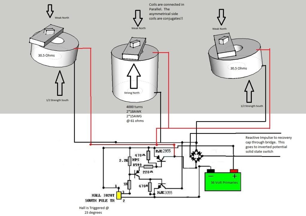
    I have been forcing my mind to think asymmetrical as much as possible here. I have created an image of base coil operation as a start. You should notice that the side conjugate coils are not TDC. It looks to be off by about 3 to 4 inches from what I recall. Only center coil is TDC.


    Right now, my figures show...

    61ohms for the Main Base Coil and
    30.5ohms for the conjugate asymmetrical side coils.
    This will equal the 12.2 ohm total in parallel.

    The side coils are opposed pulsing a weaker south pole to create attraction, while the Main center coil is creating a huge repulsed north field when switch goes on. Very interesting non-linear arrangement to say the least. I do know there is more to learn here.

    At this point I see the half bipolar bedini/cole circuit as the switch across conjugate coils in parallel. The switch sees this as a resistive load and non-inductive when on, but yet you are able to collect the collapsing magnet reactive impulse after disengaged.

    I was looking at your Adams motor arrangement. Using the concept of your half bipolar bedini/cole circuit, I made some slight adjustments. Again, I am only learning here, but I see this as a method for switching the non-linear fields. Schematic parts will of course change accordingly.

    We are all very inspired to test and learn here. Thank you so much!

    Jeremy Burnum

    Leave a comment:


  • sucahyo
    replied
    Thanks for sharing . Do we need to also put some thought to the wiring?

    Originally posted by John_Bedini View Post
    since it is not a conventional generator you must store the charge before you discharge the capacitors to the batteries. If the timing is right the batteries charge right up to full.
    Do this energy is the same energy that some people feel around the big wheel?

    "I think he wanted everyone to feel the energy around the machine. It permeated your whole body! My jacket was vibrating!"

    Leave a comment:


  • jerdee
    replied
    Half Bipolar Bedini/Cole switching on Conjugates Coils

    Hello John,

    First of all, thank you so much for your comments above! You are truly an inspiration to us all!!!

    I have been forcing my mind to think asymmetrical as much as possible here. I have created an image of base coil operation as a start. You should notice that the side conjugate coils are not TDC. It looks to be off by about 3 to 4 inches from what I recall. Only center coil is TDC.


    Right now, my figures show...

    61ohms for the Main Base Coil and
    30.5ohms for the conjugate asymmetrical side coils.
    This will equal the 12.2 ohm total in parallel.

    The side coils are opposed pulsing a weaker south pole to create attraction, while the Main center coil is creating a huge repulsed north field when switch goes on. Very interesting non-linear arrangement to say the least. I do know there is more to learn here.

    At this point I see the half bipolar bedini/cole circuit as the switch across conjugate coils in parallel. The switch sees this as a resistive load and non-inductive when on, but yet you are able to collect the collapsing magnet reactive impulse after disengaged.

    I was looking at your Adams motor arrangement. Using the concept of your half bipolar bedini/cole circuit, I made some slight adjustments. Again, I am only learning here, but I see this as a method for switching the non-linear fields. Schematic parts will of course change accordingly.

    We are all very inspired to test and learn here. Thank you so much!

    Jeremy Burnum

    Leave a comment:


  • John_Bedini
    replied
    Bedini Big Motor

    Ren,
    The Motor/Generator is also switched at five points of the magnets all coils being series arrangement, you can see the five dots. when they line up the magnets are popped with a trigger signal in the mean time everything is shorted out flux wise.
    John


    Originally posted by ren View Post
    John Bedini or anyone else who was at the event,

    Forgive the question, it may be easily answered by someone who was there, but I wanted to know if the axial arrangement has power switched into it at any time, or does it function solely as a generator or means to charge a capacitor or backpop the primary.

    From what I gathered so far the timing wheel has 16 magnets, which means it is for triggering the radial coils at the base, ala the Bedini/Cole switch with halls, as that matches the number of poles on the circumference.

    So if the basics I have written above are correct, did anyone get a clue as to how John switches his charge OFF the axial arrangement? I see no commutation, is it solidstate? Is it NOT switched at all, perhaps permanently shorted but geometrically out of phase from the radial coils.

    Fascinating machine John. I look forward to studying it.

    Regards

    Leave a comment:


  • John_Bedini
    replied
    Bedini Big Motor

    Aaron,
    Yes the cores are bonded to the metal plate on the back.
    John


    Originally posted by Aaron View Post
    Not sure if it has been asked but are the coil cores on the regauging axle
    motor physically/electrically connected to the steel plates behind the wood
    that the coils are mounted on?

    John said the core of the large center bottom coil is connected to the metal
    shaping plate with some kind of metal or iron epoxy but what about the
    regauging coil cores?

    Leave a comment:


  • ren
    replied
    John Bedini or anyone else who was at the event,

    Forgive the question, it may be easily answered by someone who was there, but I wanted to know if the axial arrangement has power switched into it at any time, or does it function solely as a generator or means to charge a capacitor or backpop the primary.

    From what I gathered so far the timing wheel has 16 magnets, which means it is for triggering the radial coils at the base, ala the Bedini/Cole switch with halls, as that matches the number of poles on the circumference.

    So if the basics I have written above are correct, did anyone get a clue as to how John switches his charge OFF the axial arrangement? I see no commutation, is it solidstate? Is it NOT switched at all, perhaps permanently shorted but geometrically out of phase from the radial coils.

    Fascinating machine John. I look forward to studying it.

    Regards

    Leave a comment:


  • Aaron
    replied
    cores connected to metal shield?

    Originally posted by pault View Post
    The first photo shows something that JB pointed out to us - the placement of the metal plates on the front hub (a plate directly underneath the shaped magnets and another plate on the back of the wooden hub on which the coils are mounted).
    Not sure if it has been asked but are the coil cores on the regauging axle
    motor physically/electrically connected to the steel plates behind the wood
    that the coils are mounted on?

    John said the core of the large center bottom coil is connected to the metal
    shaping plate with some kind of metal or iron epoxy but what about the
    regauging coil cores?

    Leave a comment:


  • Aaron
    replied
    parallel coils shorted to each other?

    I think it is interesting the delay effect of the field shaping.

    What sticks out for me and it may or may not be relevant, but all three
    coils are in parallel. When coils are in parallel and the switch is shut off,
    it discharges slower. It is like of like having a short circuited coil.

    If you take a coil like single winding and short it to itself for example and
    put that on the ground and you run a train over it with magnets on the
    bottom like a Halbach Array for example, the magnet induces current in
    that coil, the coil charges and makes a field that repels the very magnet
    that induced the current to begin with. Anyway, the field collapses slower.

    I originally found this effect in some very old magneto books going back
    a hundred years. But it has interesting properties in other applications.

    Again, not sure if the parallel coil field delay works hand in hand with that
    magnetic field shaping delay effect - still thinking about that. And not
    sure if this parallel coil arrangement even has a delay from them being
    shorted into each other. Will have to draw it out.

    Leave a comment:


  • John_K
    replied
    Originally posted by John_Bedini View Post
    Picture of Dwell Arc and magnet spacing
    John B
    Thanks John,

    I couldnt figure why you didn't just place the hall on the perimeter of the wheel but now it makes sense. The dwell starts at 23 degrees before and after each big magnet.


    John K

    Leave a comment:


  • John_Bedini
    replied
    Bedini Big Motor

    Picture of Dwell Arc and magnet spacing
    John B
    Attached Files

    Leave a comment:


  • pault
    replied
    More pictures

    Here are some of my photos.

    The first photo shows something that JB pointed out to us - the placement of the metal plates on the front hub (a plate directly underneath the shaped magnets and another plate on the back of the wooden hub on which the coils are mounted).


    In the 2nd photo,JB also explained that the cores of the shorter side coils extended down into the wooden box, if I understood correctly, to line up with the outer edges of the iron plate underneath the big coil.


    In this 3rd photo, the mounting angle of the neo's is visible.


    Leave a comment:


  • John_K
    replied
    Originally posted by John_Bedini View Post
    John,
    Right
    John B
    Thanks John, got it. Time to get to work!


    John K.

    Leave a comment:


  • John_Bedini
    replied
    Big Bedini Motor

    Mark,
    The pictures are very plain. I understand what your saying. You must build this machine at a much different level. You can see the arrangement
    for the coils. The 3 pole monopole kit is not the same thing at all. Look at my geometry.

    I have used that switching many times and I never found what your saying.

    I have used that switch on little machines and charged big capacitors with no problem so the problem must be in the coils your using.
    Look at the wire size it makes a big difference. The three pole monopole has the wrong wire size and is way to small to do this.

    I really do not want to keep repeating myself with everybody here.

    I have told you what the machine is I have left nothing out about what I did.

    Everybody should be able to see the coil arrangement, notice the outside coils 1/2 the impedance of the big center coil Total impedance of three coils 12 .2 ohms for that machine, not the three pole monopole kit.
    [COLOR="Red"]On the monopole if you do it this way you must think about how to switch the output capacitor and use an inverted switch on the output batteries, again this is not the same machine. If you going to use the BI-POLAR SWITCH you can not trigger it like the SSG, I said it used halls.[/COLOR]

    The currents are not important here in the front-end as this current is limited by the isolation of the power supply rails by the BEDINI/COLE switch. Using the term BACK EMF is meaningless as it does not apply to this machine or any SSG.The speed of the machine is also not important, it's the overlapping of the switching that is important in the dwell angle. This is equivalent to a car distributor and it better be set right.

    The metal shield located at the bottom of the big coil allows the adjustment of the magnetic field, in other words allows you to tune the magnetic field for time delay in stored energy, so don't leave home without it.

    The size of the coils,

    The groups have never built one that big so it is a complete different world to use something that big, and that is small it should have been much bigger but the cost of that was $2500 dollars not including the iron rods and the time to wind it. The machine cost us about $30.000 to make not cheap. I had a full time machinist helping me at this project who worked through the night with me.

    I'm not going to repeat myself again study what I have said about the machine.

    John Bedini


    Originally posted by Mark View Post
    I have used the half bipolar switch on my 3 pole kit before and had very low current draw. Had 1245rpm @ 12.10 volts 7.5ma draw= .10 watt. I wasn't using hall switching, I used a trigger coil (bifilar). But what I found was that there was really nothing to recycle or collect. If I remember correctly the 10uf 250 volt cap wouldn't even charge to 2 or 3 volts. With this set up I was going for the lowest amp draw I could get though. So I assume I need to turn things up so I have something to collect.

    John states to put the diodes close to the switch? I had my diodes connect directly from the base of the 21194 to the base of the mpsa06. I didn't trim the legs down any. not sure what he means by that. Also had the bridge hooked directly to my coil wires. Should I be using something other than an 1n914 for my diodes?

    Not sure what shaping the field does, makes the rotor faster or gives better collection of spike, anyone know. And what do you use to shape the field, copper, aluminuim or steel?

    Then John says to "dump the charge in seconds according to the charge rate" are we dumping to the input battery or a secondary? Dump the charge in seconds, ok I assume that means dump it fairly quickly, a couple of seconds. According to the charge rate? Doen he want double the volts over the primary and with how big of a cap. I assume a small cap so it will fill quickly but does it matter what size?

    If I use my 3 pole kit are my cores large enough ? If we are dumping into a secondary how many batteries will I need to have so my motor can run non stop, 2,3 or 4?

    Sorry for so many question but I just want to get this working and have already tried so mant different ways without success.

    Thanks, Mark

    Leave a comment:


  • redrichie
    replied
    John,
    Is there a definitive paper or guide you have written on the Ferris Wheel that we could possibly get our hands on? Something meaty you have written that we can go by? If its all in FEG than fine, but up till now I dont think most people, including myself, quite captured what you wrote in there. I understand you have been putting it out there for a very long time. And giving us nudges, but there are too many "variations". We need ONE, get this done then add this, build to focus on. Obviously the big 10 coiler, and the other kits, are all but put together for us. Unfortunately In this day and age of instant-ness, unless we have a repeatable, dummy proof way of doing it, how do we show the masses that they dont have to be beholden to the powers that be.
    I feel we need "THE" way to wind our coils. I think that is one of the primary set-backs for a lot of people. Right about the time you've made 10 5-filar coils, they are wound wrong.
    I'm not asking for a dummed down "instructable", (though that would be really simple) but the Bedini way, type of thing would help the industrious people that are willing to put hard work into this, would be very helpful.
    I remember reading Ed L. talking about a coil, and making it more efficient. He wound the coil with a core. Then basically took a sleeve, of the same material as the core, and slid it over the coil and connected it to the core. Is this what the flaps are at the central coil on the Ferris Wheel?
    Thanks John

    Leave a comment:

Working...
X